data transmitted has a symbol rate of 1 Ms/s.
The zero crossing error is the time difference between the ideal symbol period
and the measured crossing time. This shall be less than
±
1/8 of a symbol
period.
3.2 SPURIOUS EMISSIONS
The spurious emission, in-band and out-of-band, is measured with a frequency
hopping transmitter hopping on a single frequency; this means that the synthesizer
must change frequency between receive slot and transmit slot, but
always returns to the same transmit frequency.
For the USA, FCC parts 15.247, 15.249, 15.205 and 15.209 are applicable
regulations.
For Japan, RCR STD-33 applies and, for Europe, ETSI 300 328.
3.2.1 In-band Spurious Emission
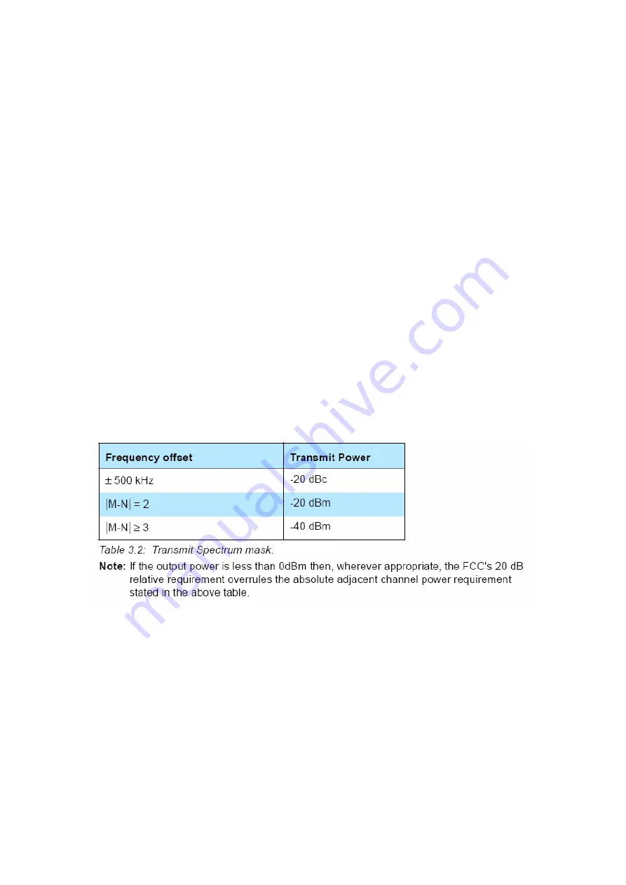
Within the ISM band the transmitter shall pass a spectrum mask, given in
Table 3.2
. The spectrum must comply with the FCC's 20-dB bandwidth definition
and should be measured accordingly. In addition to the FCC requirement
an adjacent channel power on adjacent channels with a difference in channel
number of two or greater an adjacent channel power is defined. This adjacent
channel power is defined as the sum of the measured power in a
1 MHz channel. The transmitted power shall be measured in a 100 kHz bandwidth
using maximum hold. The transmitter is transmitting on channel M and
the adjacent channel power is measured on channel number N. The transmitter
is sending a pseudo random data pattern throughout the test.
Exceptions are allowed in up to three bands of 1 MHz width centered on a frequency
which is an integer multiple of 1 MHz. They must, however, comply with
an absolute value of –20 dBm.
3.2.2 Out-of-Band Spurious Emission
The measured power should be measured in a 100 kHz bandwidth.


