background image

Bounce Flash

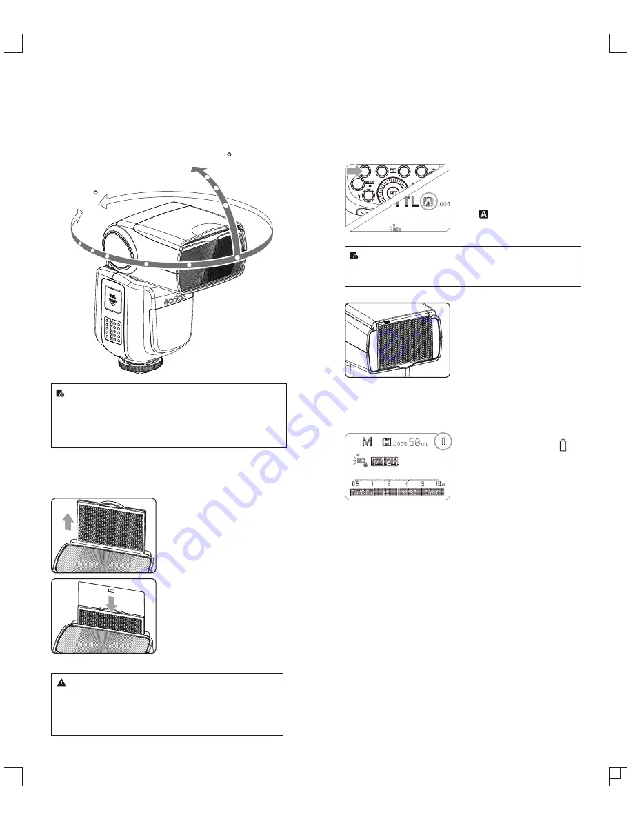
By  pointing  the  flash  head  toward  a  wall  or  ceiling,  the  flash  will 

bounce  off  the  surface  before  illuminating  the  subject.  This  can 

soften shadows behind the subject for a more natural-looking shot. 

This is called bounce flash.

To set the bounce direction, hold the flash head and turn it to a 

satisfying angle.

360

-7-90

● 

If the wall or ceiling is too far away, the bounced flash might 

be too weak and result in underexposure.

● 

The wall or the ceiling should be a plain, white color for 

high reluctance. If the bounce surface is not white, a color 

cast may appear in the picture.

Creating a Catchlight 

With the catchlight panel, you can create a catchlight in the subject’s 

eyes to add life to the facial expression. 

Point the flash head upward 

1

by 90°.

Pull  out  the  wide  panel.  The 

2

catchlight  panel  will  come  out 

at the same time.

Push the wide panel back in.

3


● 

Push in only the wide panel.

● 

Follow the same procedures 

as for bounce flash.

● 

Point the flash head straight ahead and then upward by 

90°. The catchlight will not appear if you swing the flash 

head left or right.

● 

For best catchlight effect, stay 1.5m/4.9ft away from the 

subject.

ZOOM: Setting the Flash Coverage and Using 

the Wide Panel

The flash coverage can be set automatically or manually. It can be 

set to match the lens focal length from 20 mm to 200mm (135 

system). Also, with the built-in wide panel, the flash coverage can 

be expanded for 12mm wide-angle lenses.

Choose APS or 135 system in the C.Fn-AP. 

In Manual Zoom mode, press the 

<ZOOM/C.FN> button.

● 

Turn the Select Dial to change 

the flash coverage.

● 


If <

 > is displayed, the flash 

coverage will be set 

automatically.

If  you  set  the  flash  coverage  manually,  make  sure  it  covers 

the  lens  focal  length  so  that  the  picture  will  not  have  a  dark 

periphery.

Using the Wide Panel

Pull out the wide panel and place it 

over the flash head as shown. The 

flash coverage will then be extended 

to 12 mm.

● 

The catchlight panel will come out 

at the same time. Push the 

catchlight panel back in.

● 

The <

ZOOM/C.FN

> button will not 

work.

Low Battery Warning

If the battery power is low, <


 > 

will appear and blink on the LCD 

panel. Please replace the battery 

immediately.

-  43  -

-  44  -

Содержание TT685

Страница 1: ......

Страница 2: ...flash your shooting will become simpler You can easily achieve a correct flash exposure even in complex light changing environments This camera flash features GN60 m ISO 100 200mm 22 steps from 1 1 t...

Страница 3: ...ating a Catchlight ZOOM Setting the Flash Coverage and Using the Wide Panel Low Battery Indicator C Fn Setting Custom Functions Firmware Upgrade Protection Function Technical Data Troubleshooting Main...

Страница 4: ...24 Function Button 4 Control Panel LCD Panel Name of Parts 21 22 23 15 20 18 19 16 24 17 1 TTL Autoflash Zoom zoom display Page 44 Automatic Manual Page 35 TTL TTL autoflash Focus length Page 44 High...

Страница 5: ...Rotate the lock ring on the mounting foot until it locks up Detach the Camera Flash 3 Rotate the lock ring on the mounting foot until it is loosened Power Management Use ON OFF Power Switch to power t...

Страница 6: ...n and flash exposure compensation amount will be highlighted on the LCD panel High Speed Sync High Speed Sync Hss flash enables the flash to synchronize with all camera shutter speeds This is convenie...

Страница 7: ...ct high speed mode and is displayed Set the flash frequency and 3flash times Press Function Button 3 to select the flash times Turn the Select Dial to set the number Press Function Button 4 to select...

Страница 8: ...ntrol all of them via wireless In this user manual master unit refers to the camera flash on a camera and slave unit will be controlled by the master unit Press Function Button 4 1 to choose the group...

Страница 9: ...Using Fully Automatic Wireless Flash The FEC and other settings that set on the master unit will also be appeared on the slave unit automatically The slave unit does not need any operation Use the fol...

Страница 10: ...t its receive end into the Wireless Control Port on the flash and insert the transmit end into the camera hot shoe Settings made on the hotshoe mounted transmit and receive ends will be wirelessly com...

Страница 11: ...d and then upward by 90 The catchlight will not appear if you swing the flash head left or right For best catchlight effect stay 1 5m 4 9ft away from the subject ZOOM Setting the Flash Coverage and Us...

Страница 12: ...re more flashes in short intervals the inner over temperature protection function may be activated and make the recycling time over 10 seconds If this occurs allow a rest time of about 10 minutes and...

Страница 13: ...Power saving Sync Triggering Mode Color Temperature Dimensions W x H x D Weight without battery Troubleshooting If there is a problem refer to this Troubleshooting Guide The Camera Flash cannot be cha...

Страница 14: ...onals Changes made to the specifications or designs may not be reflected in this manual Maintenance Any Changes or modifications not expressly approved by the party responsible for compliance could vo...

Отзывы: