
22
Basic Bot Guide
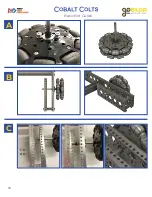
6: Adding Bearings
1504
1161
2800
x2
x2
x8
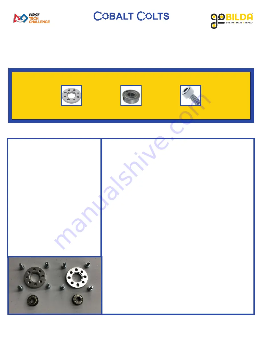
PARTS REQUIRED:
• x2 1504 Series 32mm OD Pattern
Spacer (
4mm Length
)
• x2 1611 Series Flanged Ball
Bearing (
6mm ID x 14mm OD,
5mm
)
• x8 2800 Series Socket Head Screw
(
M4 x 0.7mm, 8mm
)
INSTRUCTIONS:
A. Place each Ball Bearing inside 1 32mm Pattern Spacer. Ensure
the flange of the Ball Bearing is inset into the ridge of the Pattern
Spacer with the Bearing sticking verically upward from the
Pattern Spacer.
B. Using 4 8mm Socket Head Screws, mount one Bearing/Spacer
assembly into the fourth hole from the front of the 17-Hole Low
Side U-Channel. Ensure screw heads are exposed on the outside
of the Low Side U-Channel. Ensure Pattern Spacer is mounted
on the inside of the Low Side U-Channel with the Bearing
sandwiched between the Spacer and the U-Channel.
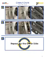
C. Repeat the previous step for the other side of the robot.
Содержание Master FTC Kit
Страница 8: ...8 Basic Bot Guide A B C Holes 1 6 Empty Hole 7 336mm goRail Holes 8 16 Empty Hole 17 336mm goRail...
Страница 9: ...9 Basic Bot Guide End of Step 1...
Страница 11: ...11 Basic Bot Guide C Repeat for a Second Wheel...
Страница 12: ...12 Basic Bot Guide End of Step 2 Shallow Side Deep Side...
Страница 14: ...14 Basic Bot Guide A B Hole 4 Hole 4 Back of Robot Front of Robot Front of Robot Back of Robot...
Страница 15: ...15 Basic Bot Guide End of Step 3...
Страница 17: ...17 Basic Bot Guide A B Repeat for the Second Wheel D shaft should be flush with the edge of the Sonic Hub...
Страница 18: ...18 Basic Bot Guide End of Step 4...
Страница 20: ...20 Basic Bot Guide A B C D Repeat for Other Bumper...
Страница 21: ...21 Basic Bot Guide End of Step 5...
Страница 23: ...23 Basic Bot Guide A B C Repeat for the Other Side...
Страница 24: ...24 Basic Bot Guide End of Step 6...
Страница 26: ...26 Basic Bot Guide A B C D...
Страница 27: ...27 Basic Bot Guide E F G Repeat for the Other Wheel Line Up D Shaft With Screw Heads Bearing No Bearing...
Страница 28: ...28 Basic Bot Guide End of Step 7...
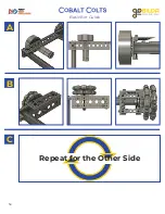
Страница 30: ...30 Basic Bot Guide A B C...
Страница 31: ...31 Basic Bot Guide D E F Repeat for the Other Side...
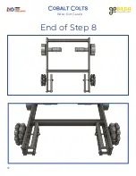
Страница 32: ...32 Basic Bot Guide End of Step 8...
Страница 34: ...34 Basic Bot Guide A B C Repeat for the Other Side...
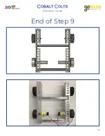
Страница 35: ...35 Basic Bot Guide End of Step 9...
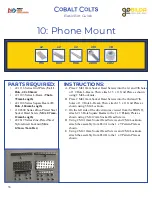
Страница 37: ...37 Basic Bot Guide C A B...
Страница 38: ...38 Basic Bot Guide D E...
Страница 39: ...39 Basic Bot Guide End of Step 10...
Страница 41: ...41 Basic Bot Guide A B C...
Страница 42: ...42 Basic Bot Guide End of Step 11...
Страница 44: ...44 Basic Bot Guide B C A...
Страница 45: ...45 Basic Bot Guide End of Step 12...
Страница 47: ...47 Basic Bot Guide A B C Top View Underside View...
Страница 48: ...48 Basic Bot Guide End of Step 13...
Страница 50: ...50 Basic Bot Guide A B C...
Страница 51: ...51 Basic Bot Guide End of Step 14...
Страница 53: ...53 Basic Bot Guide C A B...
Страница 54: ...54 Basic Bot Guide End of Step 15...
Страница 56: ...56 Basic Bot Guide A B C...
Страница 57: ...57 Basic Bot Guide D E F...
Страница 58: ...58 Basic Bot Guide End of Alternate Assembly...