


1.1 Environmental Requirement
Please make sure that AC power, PLC output modules,starters,relays and other types of
electrical interface device are far away from the back of this product.
1.3 Power Requirement
Input voltage: 12~28VDC; Starting current:180mA;Working current:130mA.
Particularly note that there must be enough distance between this product and converters
or switch mode power supply. Make sure that the input and output cables of that kind
equipment are shield cable and the shielding network is connected with the ground.
Make sure that the DC power and AC power is isolated.
Do not use common power with perceptual load or input circuit of the controller.
NOTE:
An Internal fuse will prevent damage for over voltage condition, however it isn’t guaranteed
the internal electronic components are not damaged.
Chassis ground must be used.
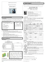
2.1 Dimensional Drawing (mm)
2.2 Fixed Screw Installation Instructions
Put the unit through the panel cut out. Slide the clamps into the 4 holes provided around the
case. Tighten the clamping screws in an even pattern until the unit is secured in the panel.
To seal to NEMA-4 specifications, all supplied mounting clamps must be used and panel
cannot flex more than 0.010"
Do not over-tighten mounting clamps!
2.3 Power Connections
Before connecting the power, please make sure all local and national electrical standards are
met. For power cables, please select cables with their dielectric strength values and current
values in compliance with the safety specifications.
First find the power terminal at the back of the product and loosen the screw according to
counterclockwise, then insert the power cables and tighten the screw up.
Connect positive DC line to the ‘+24V’ terminal and the DC ground to the ‘0V’ terminal.
3.1 DIP Switch
3.2 COM0&COM2
Pin assignment of the 9-pin male,D-SUB,COM0.This port is used to
connect the GOP41-070ET(E) to controller with RS-232/485/422 port.
Note:
RS232/485/422 communication functions are supported by
COM0.COM2 supports RS232 communication function.
Pin
Signal
COM0
PLC
[RS-485]4wire
COM0
PLC
[RS-485]2wire
COM0
PLC
[RS-232]
COM2
PC/PLC
[RS-232]
1
Rx-(B)
RS-485 Rx
RS485 B
2
RxD_PLC
RS-232 Rx
3
TxD_PLC
RS-232 Tx
4
Tx-
RS-485 Tx
5
GND
Signal Ground
6
Rx+(A)
RS-485 Rx
RS485 A
7
RxD_PC
RS-232 Rx
8
TxD_PC
RS-232 Tx
9
Tx+
RS-485 Tx
3.3 COM1
Pin assignment of the 9-pin female, D-SUB, COM1. This port is used to
connect the MT4523 series to controllers with RS-232/485/422 port.
Pi
n
Signal
PLC [RS-485]4 wire PLC [RS-485]2 wire
PLC [RS-232]
1
Rx-(B)
RS-485 Rx
RS485B
2
RxD_PL
C
RS-232 Rx
3
TxD_PLC
RS-232 Tx
4
Tx-
RS-485 Tx
SW1 SW2 Working Mode
ON
ON System Setting Mode
OFF
ON Touch Screen Calibrate Mode
ON
OFF Firmware Update and Basic Parameter Setting Mode
OFF OFF Application (Online Operation) Mode
GMTCNT GOP42-150ATE
Human Machine Interface Operatör Panel
Kurulum Talimatları
1.
Installation Note
2.
Installation Description
Please
take
shielding
measures in the following
places:
Places that exist electrostatic
or other kinds of noise
Places
of
strong
electromagnetic
Places that may be exposed
to rays
Places near the power
Please do not use in the following places:
Places direct in sunlight
Surrounding temperature and humidity beyond
the specifications
Places of temperature change sharply and
easily cause condensation
Places
that
exist
corrosive
gas
and
combustible gas
Places of much dust, dirt, salt and iron powder
Places that will be splashed water, oil and
drugs
Places that bring direct vibration and shock to
host
3. External Interface