MG 20 B
G
ÖÇ
M
AK
S
AN
3
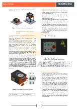
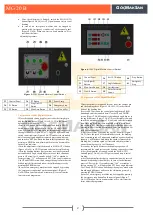
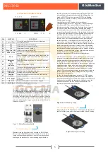
Figure 7:
220V Digital Machine Control Button
4.
TECHNICAL DATA
5.
EQUIPMENT SUPPLIED WITH
MACHINE
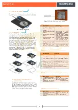
Straight Pin
: 1 ea
Stirrup Head
: 4 ea
Bending Sleeve
: 2 ea
Switch Pin
: 3 ea
Machine Table
: 1 ea (optional)
Ruler
: 1 ea (optional)
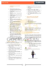
Figure 8:
Machine Table and Ruler
6.
OPERATION OF MACHINE
6.1.
Correct Positioning of Rebar On The Machine
Correct Positioning of the
rebar onto the machine by
the help of bending Tools
on single bending.
Correct Positioning of the
rebar onto the machine by
the help of bending Tools on
multiple bending.
Figure 9:
Correct Positioning of Rebar On The Machine
6.2.
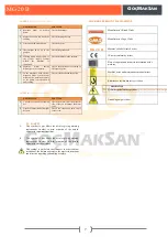
Incorrect Positioning of Rebar On The Machine
Incorrect
Positioning
of
rebar onto the machine
without using the bending
sleeve
Incorrect Positioning of rebar
onto the machine by mis-use
of stirrup head.
Incorrect Fixing of the rebar
onto the machine accroding
to the rotation of the
bending disc.
Incorrect Fixing of the rebar
onto the machine accroding
to the rotation of the bending
disc.
Figure 10:
Incorrect Positioning of Rebar On The Machine
42
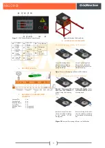
Control
Panel
46
Set 1,2,3
Button
50
Prog. Button
43
Left-
Right
Button
47
Angle
Indicator
51
Emergency
Stop
44
Man-
Auto
Button
48
Unit
Indicator
52
Speed
Controller
45
On-Off
Button
49
Value
Direction
Arrows


