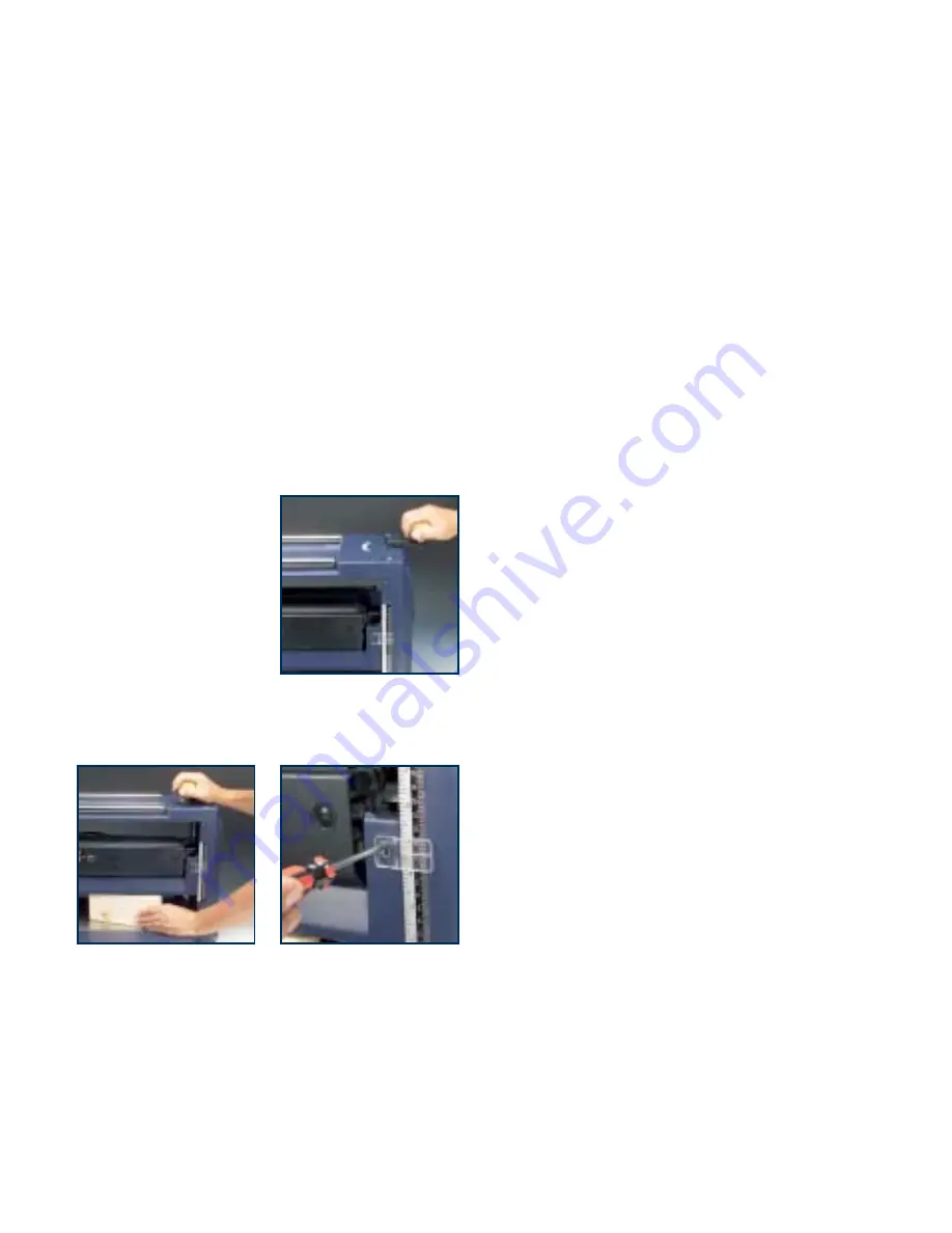
Adjusting the depth of cut
Warning.
Switch off the power and disconnect the plug
from the power point before servicing, when changing
accessories and when making adjustments.
1. The depth of cut is changed by raising or lowering the
cutter head using the height adjusting handle (2).
2. The depth scale (3) shows the height of the cutter
head above the base of the machine.
Calibrating the depth scale
Warning.
Switch off the power and disconnect the plug
from the power point before servicing, when changing
accessories and when making adjustments.
1. Raise the cutter head to
its highest position using
the height adjusting
handle (2)
2. Insert a wooden block of
known thickness (but less
than 150mm) under the
cutter head.
3. Lower the cutter head until
it just makes contact with the wooden block. Move the
block backwards and forwards across the width of the
cutter head to establish the optimum adjustment.
4. Loosen the screws securing the adjustable depth
indicator (4), adjust the indicator so that the scale
shows the correct height and re-tighten the screws.
5. Test the reading by planing a piece of scrap timber,
note the height indicated on the depth scale (3) and
then measure the thickness of the work piece. The two
measurements should be the same. If not, re-adjust
the depth indicator (4) accordingly.
Operation
1. Adjust the depth of cut to make an initial light
(0.5mm) cut. Note that one complete revolution of the
height adjusting handle (2) is equivalent to 2mm
depth of cut.
Warning.
Never attempt to plane more than 3mm in
one pass and never attempt to plan a board which is
less than 125mm long, or more than 160mm high, or
less than 4.5mm thick.
Warning.
Always use the push stick (16) to feed a
short work piece into the machine.
2. Switch on the machine and wait until the motor has
reached full speed.
3. Press the board against the in-feed table (6) and feed
it into the machine.
4. Release the board when the machine starts to cut and
let the board feed into the machine automatically.
5. Repeat the operation taking cuts of up to 3mm until
the desired thickness is achieved. Note that the finer
the cut, the better the finish.
Avoiding snipe
1. Snipe is caused by the board tilting slightly towards the
beginning and the end of the planing operation.
2. It shows as lines at the ends of the board, parallel
with the cutter head.
3. To avoid snipe, either support the board on extension
tables set to the same level as the in-feed and out-feed
tables, or mount the machine in a recess in the bench
so that the feed tables are level with the bench.
9


