background image

10

3.  When set at right angles to 

the planer base, the fence 

provides a guide to help 

control the planing action.

Note.

 The fence can be fitted 

to either side of the base.

Note.

 The angle graduations 

marked on the fence are for 

indicative purposes only. For 

accurate bevel cutting it is necessary to measure the angle 

of the fence, make a trial cut and adjust if necessary.

Shavings extraction

1. The dust/chip extraction 

port (6) allows connection 

to a vacuum dust extraction 

system.

2. Using the dust extraction 

adaptor (18) permits a 

dust extraction system to 

be connected to the dust 

extraction port (6).

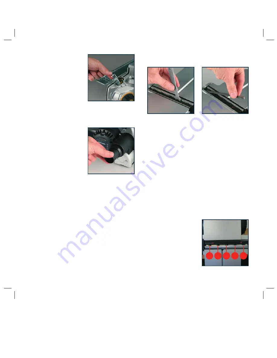
3. To fit the adaptor (18) insert it into the port (6) and twist it 

clockwise until it locks into position.

Removing and installing planer blades

CAUTION.

 Always ensure that the tool is switched off 

and unplugged from the power supply before installing or 

removing blades.
Your planer is fitted with reversible blades. Blades can be 

reversed when blunt. After both sides of the blades have 

been used they should be discarded.

Note:

 These blades cannot be re-sharpened.

Removing a planer blade
CAUTION.

 The blades are very sharp. Take care when 

handling them.

1. Using the supplied spanner (19), loosen the five clamping 

screws (11).

2. Remove the planer blade (9) from the slot in the blade 

barrel (10) in which it is retained.

Installing a planer blade

1. The blades are reversible as they have a cutting edge on 

both sides. If a blade edge is worn or damaged, the blade 

can be removed and put back the other way around. 

  Either turn over the planer blade (9) or replace it if 

required.

2. Slide the good blade face up into the blade support block 

of the blade barrel (10).

Note.

 If only one blade is damaged, it can be replaced 

without the need to replace the other two blades. When 

blades are worn, they must be replaced as a set of three to 

prevent unbalanced operation with consequential dangerous 

vibration and possible damage to the tool.

Note:

 The ridge along the blade should be on the blade 

face on the opposite side to the clamping screws (11).
3. Tighten the clamping screws 

(11), in the following manner.

  Tighten the two outside 

clamping screws snug tight, 

then the next two screws, 

then the middle screw.

  Working in the same order, 

fully tighten all five screws.

1

3

5

4

2

Order of tightening 

clamping screws

Содержание BFPCF

Страница 1: ...1 1500W CARBON FIBRE FULL WIDTH POWER PLANER BFPCF INSTRUCTION MANUAL Black Cyan Magenta Yellow Code BFPCF Date 080529 Edition 06 Op DCR ...

Страница 2: ... With continuing product development changes may have occurred which render the product received slightly different to that shown in this instruction manual Please ensure that you store your receipt in a safe place Conditions apply to the above warranty For full details of the warranty terms and conditions please refer to our website www gmcompany com For prompt service we suggest you log your ser...

Страница 3: ...ction Your new GMC power tool will more than satisfy your expectations It has been manufactured under stringent GMC Quality Standards to meet superior performance criteria You will find your new tool easy and safe to operate and with proper care it will give you many years of dependable service CAUTION Carefully read through this entire Instruction Manual before using your new GMC Power Tool Take ...

Страница 4: ...se reduces the risk of electric shock 3 Personal safety a Stay alert watch what you are doing and use common sense when operating a power tool Do not use a power tool while you are tired or under the influence of drugs alcohol or medication A moment of inattention while operating power tools may result in serious personal injury b Use safety equipment Always wear eye protection Safety equipment su...

Страница 5: ...nsion cable is required you must ensure that it has the right ampere rating for your power tool and is in safe electrical condition Ensure your mains supply voltage is the same as your tool rating plate voltage After long working periods external metal parts and accessories could be hot If possible always use clamps or a vice to hold your work Always switch off before you put the planer down Do no...

Страница 6: ...structions to be found in this Manual All persons who use and service the machine have to be acquainted with this Manual and must be informed about its potential hazards Children and frail people must not use this tool Children should be supervised at all times if they are in the area in which the tool is being used It is also imperative that you observe the accident prevention regulations in forc...

Страница 7: ...b x 2 8 Fence attachment point x 4 9 Reversible blades 10 Blade barrel 11 Clamping screw x 5 12 Moveable front base 13 Fixed rear base 14 Combined parallel and bevel fence guide 15 Front handle lock lever 16 Front handle set screw 17 Drive belt cover 18 Dust extraction adaptor 19 Blade spanner 20 Spare drive belt 8 3 1 2 4 5 7 6 8 9 10 11 12 13 14 15 18 19 20 16 17 ...

Страница 8: ...e the difference in thickness and adjust the setting if necessary Switching on and off CAUTION Before plugging the machine into the power point always check that the trigger switch 1 and lock off button 2 work properly Before switching on ensure that the blade drum is not making contact with any surface 1 Plug in the machine push in the lock off button 2 and pull the trigger switch 1 2 To stop the...

Страница 9: ...f you incline the workpiece slightly away from you so that you plane downhill CAUTION Moving the machine too fast may cause a poor quality of cut and can damage the blades or the motor Moving the machine too slowly may burn or mar the cut The proper feed rate will depend on the type of material being cut and the depth of the cut Practice first on a scrap piece of material to gauge the correct feed...

Страница 10: ...nnot be re sharpened Removing a planer blade CAUTION The blades are very sharp Take care when handling them 1 Using the supplied spanner 19 loosen the five clamping screws 11 2 Remove the planer blade 9 from the slot in the blade barrel 10 in which it is retained Installing a planer blade 1 The blades are reversible as they have a cutting edge on both sides If a blade edge is worn or damaged the b...

Страница 11: ...o the operator and others in the vicinity Note Your planing surface will end up rough and uneven unless the blades are set and secured properly The examples below show proper and improper settings Correct setting Correct setting clean smooth cut Nicks in surface as caused by the edge of one or all blades not being parallel to the surface of the rear base Gouging at start as caused by the edge of o...

Страница 12: ...nsure that the tool is switched off and the plug is removed from the power point before making any adjustments or maintenance procedures Regularly check that all the fixing screws are tight They may vibrate loose over time Cleaning 1 Keep the tool s air vents unclogged and clean at all times 2 Remove dust and dirt regularly Cleaning is best done with compressed air or a dry soft to medium brush li...

Страница 13: ...13 ...

Страница 14: ...14 ...

Страница 15: ...15 ...

Страница 16: ...land 7am 7pm 7days a week AEST Please note that if repair is required you must provide a valid original purchase receipt You will need the following details at hand to log your service request Personal details First Last name address pick up address contact phone numbers email address Product details Product number date of purchase retailer bought from State postcode receipt number reason for the ...

Отзывы: