Glow-worm ULTIMATE 30BF Скачать руководство пользователя страница 6

6

221788B

1 General Data

1.5 Gas Supply

The gas installation shall be in accordance with the current
issue of BS6891.

The supply from the governed meter must be of adequate size
to provide a steady inlet working pressure of 20mbar (8in wg) at
the boiler.

On completion test the gas installation for soundness using the
pressure drop method and suitable leak detection fluid, purge
in accordance with the above standard.

1.6 Electrical Supply

WARNING.  This boiler must be earthed.

All system components shall be of an approved type and shall
comply with and be connected in accordance with the current
issue of BS7671 and any applicable local regulations.

Connection of the boiler and system controls to the mains
supply must be through a common isolator and must be fused
3A, maximum.  This method of connection must be by a fused
double pole isolating switch, with a minimum contact separation
of 3mm on both poles.  The switch should be readily accessible
and preferably adjacent to the appliance.  It should supply the
appliance only and be easily identifiable as so doing.

Alternatively, an unswitched shuttered socket outlet and 3A
fused 3 pin plug both to the current issue of BS1363 may be
used, provided that they are not used in a room containing a
bath or shower.

Wiring to the boiler must be PVC insulated type to the current
issue of BS6500 Table 16, not less than 0.75mm

2

 (24/0.20mm).

1.7 Contents of Packaging

There are two packs, one contains the boiler, refer to Section 4.1
for contents.

The other pack contains the balanced flue terminal assembly,
wall duct and flue hood assembly.

Refer to Section 2.3 to check that the flue terminal assembly
supplied is suitable.

1.8 Water System

This boiler shall only be used on an unrestricted open vented
system with the water supply taken from a feed and expansion
cistern having a head of 27m (90ft) maximum.

This boiler must not be connected to a sealed water system.
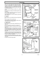
1.9 Drain

System

A draining tap must be provided at the lowest points of the
system which will allow the entire system, boiler and hot water
cylinder to be drained.

Draining taps should be to the current issue of BS2879.

Boiler

A draining point is fitted at the bottom right hand side of the heat
exchanger. Cover controls to avoid water damage. If required
remove the combustion chamber front cover to improve access.

RANGE RATING

NOMINAL

kW

HEAT
INPUT

(GROSS)

Btu/h

NOMINAL

kW

HEAT
OUTPUT

Btu/h

BURNER

m bar

SETTING
PRESSURE

in.w.g

APPROX

m

3

/h

GAS
RATE

ft

3

/h

TABLE 2.

7.52

9.25

10.99

25,650

31,575

37,500

5.86

7.33

8.79

20,000

25,000

30,000

5.5

9.1

12.7

2.2

3.7

5.1

0.72

0.89

1.06

25.5

31.5

37.5

min

medium

max

2.35Litre
(0.52gal)

44.5kg
(98lb)

34kg
(75lb)

DATA TABLE 1.

DATA LABEL

Bottom right hand side of case

ELECTRICITY
SUPPLY

WATER
CONNECTION

GAS
CONNECTION

WATER
CONTENT

LIFT WEIGHT

( I n c l u d i n g
Terminal)

TOTAL DRY

4 x 22mm copper  pipes from

top of case

Rc 

1

/

2

 in.

230V~50Hz, fused 3A.

WEIGHT

BURNER INJECTOR MARKING: 203099

PILOT INJECTOR MARKING:  7215

1.10 Safety Valve

A safety valve need not be fitted to an open vented system.

1.11 Location

This boiler is not suitable for outdoor installation.

This boiler may be installed in any room, although particular
attention is drawn to the requirements of the current issue of
BS7671 with respect to the installation of a boiler in a room
containing a bath or shower.  Any electrical switch or boiler
control utilising mains electricity should be  placed so that it
cannot be touched by a person using the bath or shower.
The electrical provisions of the Building Standards (Scotland)
Regulations apply to such installations in Scotland.

The boiler must be mounted on a flat wall which is sufficiently
robust to take its total weight.

Содержание ULTIMATE 30BF

Страница 1: ...ephoning the Heatcall Customer Service number 01773 828100 Our Guarantee gives you peace of mind plus valuable protection against breakdown by covering the cost of Guarantee Registration Balanced Flue Boiler This is a Cat I2H Appliance BS 6332 BS 5258 Reference in these instructions to British Standards and Statutory Regulations Requirements apply only to the United Kingdom The instructions consis...

Страница 2: ... The CE mark on this appliance shows compliance with 1 Directive 90 396 EEC on the approximation of the laws of the Member States relating to appliances burning gaseous fuels 2 Directive 73 23 EEC on the harmonization of the Laws of the Member States relating to the electrical equipment designed for use within certain voltage limits 3 Directive 89 336 EEC on the approximation of the Laws of the Me...

Страница 3: ...e recorded in your boiler Logbook You can check your installer is CORGI registered by calling CORGI direct on 01256 372300 Cleaning WARNING This boiler contains metal parts components and careshouldbetakenwhenhandlingandcleaning withparticular regard to edges Clean the casing occasionally by wiping it over with a damp soapy cloth or dry polishing duster Do not use an abrasive cleaner Protection Ag...

Страница 4: ...pilot fails to stay alight a safety device prevents immediate relighting Do not attempt to relight until the safety device has reset that is for at least three minutes Switch on the electrical supply and check that all external controls are calling for heat Turn the control thermostat knob B clockwise to any position between MIN and MAX and the burner will light The maximum setting is about 82o C ...

Страница 5: ...contained in the current issue of the following British Standards and Codes of Practice BS6798 BS5440Part1and2 BS5546 Part1 BS5449 BS6891 BS6700 BS7593 BS7478 BS7671 Manufacturer s instructions must not be taken as overriding statutory requirements 1 2 Data See Table 1 The Seasonal Efficiency Domestic Boilers UK SEDBUK is 72 2 ThevalueisusedintheUKGovernment sStandardAssessment Procedure SAP for e...

Страница 6: ...system with the water supply taken from a feed and expansion cistern having a head of 27m 90ft maximum This boiler must not be connected to a sealed water system 1 9 Drain System A draining tap must be provided at the lowest points of the system which will allow the entire system boiler and hot water cylinder to be drained Draining taps should be to the current issue of BS2879 Boiler A draining po...

Страница 7: ...especialconsiderationwithrespecttoanyopenings doors vents or windows under the roof Care is required to protect the roof if it is made of plastic sheeting If the car port consists of a roof and two or more walls seek advice from the local gas company before installing the boiler If the terminal is fitted within 600mm below plastic guttering or painted soffit an aluminium shield 1500mm long should ...

Страница 8: ...a timber frame building it should be fitted in accordance with the Institute of Gas Engineers documentIGE UP 7 1998 Ifindoubtseekadvicefromthelocal gas undertaking or Hepworth Heating Ltd Diagram 2 1 A DIRECTLY BELOW AN OPENABLE WINDOW AIR VENT OR ANY OTHER VENTILATION OPENING 300 B BELOW GUTTER DRIAN SOIL PIPE 300 C BELOW EAVES 300 D BELOW A BALCONY OR CAR PORT 600 E FROM VERTICAL DRAIN PIPES AND...

Страница 9: ... 2 metres away from the boiler The flow through the boiler must not be allowed to fall such that thereisatemperaturedifferencegreaterthan20o Cbetweenthe flow and return 3 4 Water System The cold feed must be 15mm minimum size It is important that the relative positions of the pump cold feed and open vent are as shown in diagram 3 2 Theunrestrictedopenventfromtheboilermustrisecontinuously to discha...

Страница 10: ...nd Domestic Hot Water The connections for this type of system MUST be as shown in diagram 3 2 and 3 4 3 9 Inhibitor Attention is drawn to the current issue of BS5449 and BS7593 on the use of inhibitors in central heating systems If an inhibitor is to be used contact a manufacturer or Hepworth Heating Ltd for their recommendations as to the best product to use When installing in an existing system ...

Страница 11: ...be faced off to the hole dimensions shown Use template again making sure that it is positioned both square and central to the flue hole marking the fixing points at the top bottom and clearance holes for wall duct Remove the wall template after marking then check marked positions against diagram 4 3 Drill holes to accept the plugs and screws supplied in the loose items pack Secure the bottom brack...

Страница 12: ... Diagram 4 4 3797 C L C L 168 122 122 112 112 FIXING POINTS FIXING POINTS FLUE HOLE CLEARANCE HOLE 2 420 35 119 119 220 325 3798 5mm wall plug No 12 X 2 long woodscrew 7mm dia drill WALL DUCT CLEARANCE HOLES SECURING SCREWS 2 SECURING CLIPS MOUNTING BRACKET ...

Страница 13: ... hole in the wall fit it around the wall duct slide in until the wall plate touches the wall surface Make sure the air duct wire guards are in position Sealthejointintheairductswiththeyellowtapeprovided Tape four pieces into the four inside corners followed by four along the joints overlapping the corner pieces to make a good seal see diagram 5 4A Allow a minimum of 20mm 3 4 in overlap of the duct...

Страница 14: ...SEMBLY Inner Baffle Flue Duct 5 2 Water Circulation System Complete the water connections to the boiler Fill vent and cold flush the system as recommended in the current issue of BS6798 Check for any water leaks and put right 5 3 Gas Connection Make the gas connection to the Rc1 2 in gas service cock Check for leaks using a suitable leak detection fluid 5 4 Control Box Remove the electrical contro...

Страница 15: ... clamp Make sure the cable is suitably secured When making connections make sure that the earth conductor is made of a greater length than the current carrying conductors so that if the cable is strained the earth conductor would be the last to become disconnected 5 6 Testing Checks to ensure electrical safety must be carried out by a competent person After installation of the system preliminary e...

Страница 16: ... FUNCTIONAL CONTROL CABLE EARTH TERMINAL CONTROL THERMOSTAT THERMOSTAT CAPILLARY MAINS CABLE 8051 8038 MULTI FUNCTIONAL CONTROL CONTROL THERMOSTAT KEY br BROWN g y GREEN YELLOW bl BLUE bk BLACK 230V 50Hz MAINS SUPPLY FUSED AT 3A N L L N g y g y g y bk br bl br bk bl EARTH HOOK CONTROL BOX COVER ...

Страница 17: ...urner lights keep the button K pushed in for 20 seconds If the pilot fails to stay alight a safety device in the multi functional control prevents immediate relighting Do not attempt to relight until the safety device has reset that is after a minimum of three minutes Make sure that the pilot is alight and stable view through window H Check the length of the pilot flame it should envelop the therm...

Страница 18: ...ttempt to adjust the control thermostat calibration 6 5 Thermostatic Radiator Valves If thermostatic radiator valves are fitted care must be taken to make sure that an adequate flow rate through the boiler when they close refer to the current issue of BS7478 for guidance 6 6 Completion Fit the controls cover by hooking into the sliders and pushing it back as far as it will go see diagram 6 3 6 7 P...

Страница 19: ...ueway access door by removing the screws see diagram 8 1 Remove the combustion chamber front see diagram 8 1 Disconnect the pilot pipe union connector and ignition lead see diagram 8 2 Separate the pilot assembly from the main burner by removing the pilot shield securing nut shakeproof washer and move to theright Removetheburnersecuringnutandwingnutfromthe burnersupportbracket removetheburnersuppo...

Страница 20: ... for cleaning do not use a wire or sharp instrument on the hole Use a little suitable sealant on the external thread when refitting to make sure a gas tight seal is made 8 5 Electrode Pilot Burner and Pilot Injector Release the thermocouple by removing the spring clip pull the thermocouple down from the pilot assembly see diagram 8 2 Inspect and clean pilot burner assembly Remove the pilot injecto...

Страница 21: ...ontrol knob is released Does pilot flame envelope thermocoupling Check aeration If necessary Clean pilot rectify blockage in pilot injector or replace Check thermocoupling circuit using Thermocoupling Fault Finding diagram On pressing piezo unit button is there a spark across electrode gap Pull ignition lead off electrode Hold end of lead close to pilot burner and operate piezo unit Is there a spa...

Страница 22: ...ilot now stay alight Change multi functional control YES NO YES NO NO 3816 MULTI FUNCTIONAL CONTROL CONNECTION A 9 1 Pilot Refer to Chart 9 1 9 2 Thermocouple To test the thermocouple a meter with a range of 6 to 30mV is required together with a thermocouple interrupter test unit Refer to thermocouple fault finding chart diagram 9 2 and diagram 9 2A 9 3 Electrical Important On completion of the se...

Страница 23: ...n burner light Replace multi functional control harness YES NO YES NO Ensure that all services are available at the appliance ie Gas Electricity Water Also turn control thermostat fully on and check to see if pilot is lit Restore supply Is there 230V between L N on multi functional control Faulty multi functional control Renew Does pump run CONTROLS IN ORDER MAIN TERMINALS STRIP Isolate supply Rem...

Страница 24: ...at body Release the control thermostat body by unscrewing the two screws and shakeproof washers in the front of the control box Remove the split pin and withdraw the control thermostat phial from its pocket Remove the control thermostat complete from the boiler Re assembly note When fitting the control thermostat make sure that the control thermostat phial is covered with heat sink compound and th...

Страница 25: ...ioning Refit multi functional control cover 10 7 Solenoid diagram 10 4 With the multi functional control cover removed disconnect the electrical leads remove the retaining clip and solenoid 10 8 Main Burner Remove the main burner as Section 8 2 10 9 Main Injector Remove the main injector as Section 8 4 10 10 Insulation diagram 10 5 Combustion Chamber Front RemovethecombustionchamberfrontasSection ...

Страница 26: ...STION CHAMBER FRONT INSULATION REAR INSULATION PANEL Diagram 10 6 SELF ADHESIVE ALUMINIUM FOIL GASKET MICA WINDOW PEEL OFF BACKING PAPER OPENING INSIDE FACE OF THE BOILER FRONT COVER 7907 10 12 Case Seal To remove the seal carefully bend up the tabs Remove the seal making sure that all the old adhesive is removed When fitting the new seal make sure that it fits into the corners and has not buckled...

Страница 27: ...99 Thermostat control 313 915 10 204687 Control knob 11 202713 Piezo igniter 12 801236 Mica window and gasket 8048 1 5 8 6a 4 6 12 3 10 9 7 2 11 Key No Part No Description GC Part No 11 1 Part Identification The key number on the diagram and the list will help to identify the part 11 2 Ordering When ordering any spare parts please quote the number and description from the list together with the mo...

Страница 28: ...28 221788B Because of our constant endeavour for improvement details may vary slightly from those shown in these instructions ...

Отзывы: