Glow-worm Hideaway 80B FF Скачать руководство пользователя страница 27

27

221958B

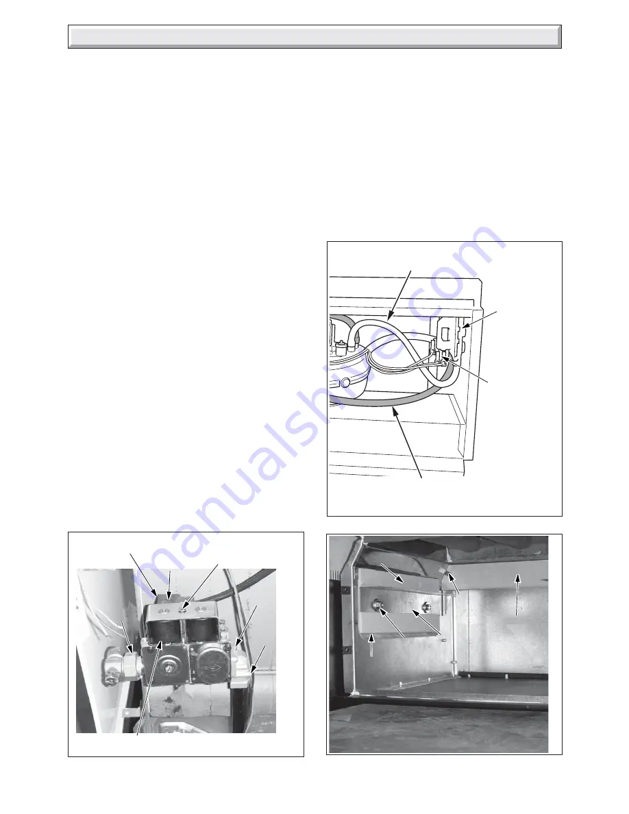
10  Replacement  of  Parts

Diagram 10.6

REAR
INSULATION
PANEL

SECURING
NIB

SIDE
INSULATION

0000

Diagram 10.4

GAS
SERVICE
COCK
UNION

ELECTRICAL
PLUG

SHORT
SCREWS (2)

LONG
SCREWS
(2)

SOLENOID
SECURING SCREW

SOLENOID ASSEMBLY

BURNER
SUPPORT
BRACKET

NUTS

10.5 Solenoid

Remove the electrical plug from the multifunctional control and
remove the securing screw and then the solenoid assembly,
see diagram 10.4.

10.6 Burner

Refer to the relevant paragraphs of the servicing section to
remove the burner from combustion chamber.

10.7 Injector

Refer to the relevant paragraphs of the servicing section to
remove the burner from combustion chamber.

The injector can then be unscrewed from the manifold.

When replacing use a little jointing compound on the external
thread only, to ensure a gas tight seal.

10.8 Air Pressure Switch

Remove front panel to gain access, see section 6.8.

Refer to the relevant paragraphs of the servicing section to
remove the burner from combustion chamber.

Remove the air pressure tubes and electrical connections from
the switch, release the securing screws and remove the switch,
see diagram 10.5.

When fitting the replacement make sure that the air pressure
tubes are fitted with the clear tube from the air pressure switch
to the front fan connection, as shown in diagram 10.5 and the
electrical connections are made as shown in wiring diagram
9.4.

10.9 Fan

Remove front panel to gain access, see section 6.8.

Refer to the relevant paragraphs of the servicing section to
remove the burner from combustion chamber.

Remove the electrical connections and air pressure tubes from
the fan.

Note: Remove the electrical connections by pulling insulation
boots only.

Undo the screw securing the fan to the flue hood and disengage
fan from flue hood.

When re-assembling, make sure that the air pressure tubes are
fitted as before and that the fan duct  engages fully into the flue
duct extension piece.

The polarity of the electrical connections is not important.

SECURING
SCREW

Diagram 10.5

10259

FRONT AIR PRESSURE
SWITCH TUBE (CLEAR)

AIR
PRESSURE
SWITCH

ELECTRICAL
CONNECTORS

REAR AIR PRESSURE
SWITCH TUBES (RED)

10.10 Insulation

Refer to the relevant paragraphs of the servicing section to
remove the burner from combustion chamber.

Sides

Undo the burner support bracket nuts and remove support
bracket and insulation, see diagram 10.6.

Refit support bracket with new side insulation.

Rear

Bend forward rear insulation securing nibs, one on each side,
to release insulation.

Fit new insulation and bend back securing nibs.

Содержание Hideaway 80B FF

Страница 1: ...r Service number 01773 828100 Our Guarantee gives you peace of mind plus valuable protection against breakdown by covering the cost of Guarantee Registration Balanced Fanned Flue Boiler This is a Cat I2H Appliance Reference in these instructions to British Standards and Statutory Regulations Requirements apply only to the United Kingdom For Ireland the rules in force must be used The instructions ...

Страница 2: ...provide information on substances hazardous to health Ceramic fibre Insulation Pads Glassyarn These can cause irritation to skin eyes and the respiratory tract If you have a history of skin complaint you may be susceptible to irritation High dust levels are usual only if the material is broken Normal handling should not cause discomfort but follow normal good hygiene and wash your hands before eat...

Страница 3: ...pendupon the particular installation conditions and usage but in general once a year should be enough It is the law that servicing must be carried out by a competent person If this appliance is installed in a rented property there is a duty ofcareimposedontheownerofthepropertybythecurrentissue of the Gas Safety Installation and Use Regulations Section 35 To obtain service please call your installe...

Страница 4: ...rol wait at least 30 seconds before switching on again When the boiler switches off the burner will go out The automatic lighting sequence will operate again when heat is required It should be noted that this is a fanned flue appliance and fan operation may be heard If the reset neon lights turn the boiler temperature control to 0 off wait 30 seconds then repeat the lighting instructions To Turn t...

Страница 5: ... in millimetres except as noted Approximate weight of complete boiler 131 5kg 290lb Water content 5 76 litre 1 27gallons Gas connection Rc1 2 1 2 in BSPT Water connection Rc1 1in BSPT Electrical supply 230V 50Hz fused 3A Burner Aeromatic GENERAL DIMENSIONS given in millimetres Diagram 1 1 9921 WATER CONNECTIONS Rc1 1in B S P T WATER CONNECTIONS Rc1 reduced with DISTRIBUTOR TUBE to Rc 3 4 3 4 in B ...

Страница 6: ...ssue of BS6891 The supply from the governed meter must be of adequate size to provide a steady inlet working pressure of 20mbar 8in wg at the boiler On completion test the gas installation using the pressure drop method and suitable leak detection fluid purge in accordance with the current issue of BS6891 1 6 Electrical WARNING This boiler must be earthed The electrical installation must be carrie...

Страница 7: ... installation of the boiler will be in an unusual location special procedures are necessary the current issue of BS6798 gives detailed guidance on this aspect 2 Water Systems 2 1 Water Pressure Head The boiler shall only be connected to a cistern water supply with a minimum head of 1metre 3ft3in and a maximum head of 27metres 90ft which has an open vent in the system The working pressure must be w...

Страница 8: ...pedflow rate the pressure loss through the boiler can be found from the graph diagram 2 3 Use a pump with integral valves or fit isolating valves as close to the pump as possible 2 6 Cylinder For all systems supplying domestic hot water the cylinder must be indirect 2 7 Safety Valve A safety valve need not be fitted to an open vented system 2 8 Draining Tap A draining tap must be provided at the l...

Страница 9: ...e from the local gas undertaking or Hepworth Heating Ltd 3 3 Terminal Guard A terminal guard is required if persons come into contact with the terminal or the terminal could be subject to damage If a terminal guard is required it must be positioned to provide a minimum of 50mm clearance from any part of the terminal and be central over the terminal A suitable guard reference Type K3 can be obtaine...

Страница 10: ...n optional wall liner kit part no 900862 is available complete with instructions All flue assemblies are designed for internal installation Make sure that the ductings do not slope down towards the boiler Diagram 4 1 9867 9868 4 2 Flue Position and Length Select the boiler location with due regard to the flue length and terminal position see diagrams 3 1 and 4 1 For a wall thickness up to 300mm pr...

Страница 11: ...nal restrictor and secure with locking screw but do not tighten see diagram 4 5 Engage the terminal restrictor on the flue terminal by hooking it over the terminal end and engaging the clamping bracket behind the inner ring of the terminal securing it by tightening the locking screw see diagram 4 5 9869 SCREW 4 SPIGOT GASKET FLUE BAYONET CONNECTION Diagram 4 4 7148 OPTIONAL FLUE COLLAR 4 Installat...

Страница 12: ...of the three remaining lower connections may be used for the gravity domestic hot water return Fit plugs into any unused boiler tappings 4 7 Water Connections Fully Pumped Systems Fit suitable fittings into the boiler tappings as required see diagram 4 9 Make sure that all pipes are taken backwards and will clear the casings It is important that all connections are made as shown in diagram 4 9 Fit...

Страница 13: ...re that it will clear the boiler air duct and if working to minimum clearance does not project too far from the boiler see diagram 4 11 Do not route any pipework water or gas across the front of the combustion chamber cover The gas pipework must be along the left hand side of the boiler 4 Installation No 8 SCREW 4 4 9 Casing Brackets Fit the two upper and two front casing brackets shown in diagram...

Страница 14: ...tory with the control box and heat shield fitted in the lower casing height position 9863 SIDE CASINGS FITTING Diagram 4 14 MAX SIDE CASING R H MIN BOILER PLINTH FRONT CASING BRACKET No 8 SCREW 4 LOCATING SLOTS 4 Installation Diagram 4 13 Diagram 4 15 SCREW SIDE CASING R H SHOWN UPPER CASING BRACKET PLASTIC PEG PLASTIC PEG SPRING CLIP SIDE CASING R H SHOWN UPPER VIEW LOWER VIEW SPRING CLIP SIDE CA...

Страница 15: ...the fittings pack Connect the flue spigot and gasket to the rear flue outlet of the boiler using the self tapping screws provided see diagram 4 3 IMPORTANT WithregardstotheManual HandlingOperations 1992 Regulations the following operation exceeds the recommended weight for one man lift Place the boiler in position taking care not to damage the casing panels With access to the flue system through t...

Страница 16: ...ervice cock at the lower left hand side of the boiler see diagram 1 1 The whole of the gas installation including the meter should be inspected tested for soundness and purged in accordance with the current issue of BS6891 4 14 Top Casing Refer to diagram 4 21 Fit two plastic pegs one on each side in the holes on the top casing Theplasticpegsareatightfitandarebestpushedhome with a flat faced tool ...

Страница 17: ...lamp Make sure the cable is suitably secured When making connections make sure that the earth conductor ismadeofagreaterlength thanthecurrentcarryingconductors so that if the cable is strained the earth conductor would be the last to become disconnected 5 3 Pump Connection The pump must be connected to the external controls 5 4 Testing Electrical Checks to ensure electrical safety must be carried ...

Страница 18: ...PONENTS 10052 A CONTROL BOX B PHIAL POCKET C GAS SERVICE COCK D BURNER ON NEON E RESET NEON F TEMPERATURE CONTROL G BURNER PRESSURE TEST POINT H GAS PRESSURE ADJUSTMENT SCREW J DATA LABEL E D A G Turn the boiler temperature control clockwise to Max The ignition system will operate to light the boiler After a pre set time if ignition has not taken place the boiler will shutdown To re start the ligh...

Страница 19: ...etting Turn the boiler temperature control fully anti clockwise to 0 Isolate from the electrical supply Remove the pressure gauge from the test point and refit screw making sure a gas tight seal is made Whentheboilertemperaturecontrolisturnedtothe 0 position by hand wait at least 30 seconds before turning On again Theremaybeaninitialsmellgivenofffromtheboilerwhennew this is quite normal and it wil...

Страница 20: ... operate on mains voltage terminals will become live Switch on the electrical supply and gas supply then operate the boiler On completion of the test switch off the electrical supply and gas supply remove analyser tube and replace sampling point cap Servicing Before servicing turn off the gas and isolate the electrical supply to the boiler After completing a service always test for gas soundness m...

Страница 21: ... sliding back to disengage the retaining lugs then lift up see diagram 8 7 Remove the flue hood When replacing the flue hood ensure that it rests on the guides and that the rear of flue hood is located under the pegs at the rear and pushed down and back fully IMPORTANT When re fitting fan check that it fits fully into the flue duct extension piece COMBUSTION CHAMBER COVER IGNITION AND EARTH LEADS ...

Страница 22: ...ng the relevant instructions in sections 8 3 and 8 4 8 3 Burner and Injector Remove the two screws and nuts securing the burner support bracket to the combustion chamber cover see diagram 8 9 Remove the graphite coated nuts on the supply feed pipe at the rear of the burner to release the burner see diagram 8 10 Clean the burner Use a vacuum cleaner or suitable stiff brush not wire to clean the bur...

Страница 23: ...ault persists continue with fault finding below Before carrying out fault finding ensure that gas electricity and water are available at the boiler Is neon 1 lit NO Check power supply Is neon 2 lit NO YES YES Faulty thermistor Replace With electrical supply isolated disconnect the 2 way thermistor plug from the PCB Check that there is a resistance between 14k 2 5kOhms Faulty PCB Replace Is neon 3 ...

Страница 24: ...ove the control box cover refer to section 5 1 Refer to Boiler Fault Finding see diagram 9 1 Fault Finding Wiring Diagram see diagram 9 3 Pictorial Wiring Diagram see diagram 9 4 9 2 Electrical Supply Failure Failure of the electrical supply will cause the burner to go out Operationwillnormallyresumeontherestorationoftheelectrical supply Iftheburnerdoesnotrelightafteranelectricalsupplyfailureand t...

Страница 25: ... 3 NEON 4 NEON 5 NEON 6 NEON KEY see P C B FAN P C B CONTROL BOARD GAS CONTROL VALVE TERMINAL BLOCK THERMISTOR AIR PRESSURE SWITCH NEON 1 NEON 5 NEON 4 NEON 6 NEON 2 NEON 3 F4A FUSE p y g p b bk bk bk bk b bk b r g y bk b LS LIVE Switched N LS N br r g y g y g y g y br b b br BROWN b BLUE g y GREEN YELLOW g GREY bk BLACK p PURPLE y YELLOW r RED KEY g y NEUTRAL EARTH MAIN KEY TO TERMINAL BLOCK br ...

Страница 26: ... Control Board P C B Remove front panel to gain access see section 6 8 Remove control box lid by undoing the four securing screws two on control box two on the heat shield and lift off see diagram 10 1 CONTROL BOX COVER CONTROL BOX SECURING SCREWS TERMINAL BLOCK Diagram 10 1 9905 ELECTRICAL PLUGS Diagram 10 2 PCB Diagram 10 3 PHIAL POCKET THERMISTOR 0000 BOILER TEMPERATURE CONTROL Carefully pull t...

Страница 27: ...t the air pressure tubes are fitted with the clear tube from the air pressure switch to the front fan connection as shown in diagram 10 5 and the electrical connections are made as shown in wiring diagram 9 4 10 9 Fan Remove front panel to gain access see section 6 8 Refer to the relevant paragraphs of the servicing section to remove the burner from combustion chamber Remove the electrical connect...

Страница 28: ...ng any spare part please quote the part number and the description from the list together with the model name and serial number information from the data label The data label is positioned on the heat shield see diagram 6 1 Key No Part No Description GC Part No 1 2000461752 Multifunctional control 2 227132 Fan 3 2000461994 Air pressure switch 4 2000461985 Electrical thermistor 5 202635 Spark elect...

Отзывы: