

eng
Green dot: The sensor is working properly
Red dot: The sensor is not able to connect to the
Gateway:
• Please check the battery status;
• Check to ensure the correct serial number has
been entered into the APP.
• In case of a weak or a bad signal, relocate the
battery sensor.
“OK”: The battery power bank voltage is above
the fixed threshold
“LOW”: The battery power bank voltage is
below the fixed threshold and, if the gateway
is connected to internet you will receive a push
notification on the APP.
9. When the red LED stops flashing, the
ZigBoat™ Battery Sensor has successfully
joined the ZigBoat™ network.
To check the correct configuration, select the
Overview tab of the ZigBoat™ App. (fig. 6)
Resetting
Resetting is needed if you want to connect
your ZigBoat™ Battery Sensor to another
gateway or if you need to perform a factory
reset to eliminate abnormal behavior.
The reset button is marked with the small ring
on the front of the sensor.
STEPS FOR RESETTING
1. Open the casing of the device by pushing
the fastening on top of the device to remove
the front panel from the back cover.
2. Remove the batteries (2xAAA) and reinsert
the batteries
3. Press and hold down the reset button for
approximately 8-10 seconds. The button
has to be pushed within one minute after
inserting the batteries.
4. When the red light starts flashing every
second, the reset process has been
successfully implemented.
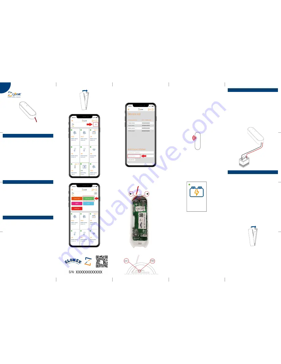
Mounting
• Place the sensor indoors at a temperature
between 0-50°C.
• Connect the red wire (+) to the positive pole
of the battery power bank.
• Connect the black wire (-) to the negative
pole of the battery power bank.
IMPORTANT:
Use one battery sensor for each
battery power bank you want to monitor
Version 1.0
OWNER’S MANUAL
Fig. 1
Fig. 2
Fig.5/
A
Fig.5/B
Fig. 3
5. Insert the enclosed batteries (2xAAA) into the
sensor making sure to observe the correct
polarity.
6. Close the casing.
7. The ZigBoat™ Battery Sensor will now start
searching for the ZigBoat™ network to join.
8. While the ZigBoat™ Battery Sensor is
searching for the ZigBoat™ network to join,
the red light on the sensor will flash.
4. The Battery Sensor is set by default to 12V
mode. To switch to 24V mode, please move
the switch as indicated in the sticker placed
in the device (fig. 5/A and 5/B).
3. You can change the device name by
selecting “Name” (fig. 4). Then, press the “Add
Device” button.
Battery Sensor
code: ZB201
• When removing sensor battery covers,
remember that electrostatic discharge can
damage electronic components inside.
• Always mount indoors.
• Do not remove the product label as it
contains important information.
Product description
The ZigBoat™ Battery Sensor monitors the
battery power bank voltage and, if it drops
below a fixed threshold sends you push
notifications.
Thanks to the switch you can use 12V or 24V
battery power bank.
NOTE: 12V mode threshold: 11.6V (± 0.3V)
24V mode threshold: 23.1V (± 0.3V)
Precautions
Adding the sensor to the Gateway
NOTE:
Make sure the gateway is turned on
and configured correctly. For more details,
please see the gateway installation manual.
1. Open the Zigboat APP, select the Gateway
in the ZB Gateways menu and wait a few
seconds. Then, select the “menu” button
on the top right (fig. 1). Select “Device list”
(fig. 2). Add the sensor by entering the serial
number which is on the sensor’s label (fig. 3).
2. To locate the serial number of the sensor,
remove the front cover by pressing the tab
on top.
OK
Battery Sensor
Battery #1
12V
24V
12V
24V
Fig. 4
Fig. 6
+
+
-
-


