G l o b a l s t a r M C M - 4 e
I N S T A L L A T I O N
6
8.
Route Ethernet Cable to planned locations of remote client equipment.
9.
Connect the Ethernet cable to clients as necessary. The MCM-4e provides one 10/100 Base-T
Ethernet (RJ45) port (
ETHERNET on front panel)
. Category 5 (Cat 5) unshielded twisted pair
(UTP) cabling will be required to be run between the MCM and remote client terminal.
RJ-45 Ethernet Cable Routing
Route the CAT5 RJ-45 Ethernet cable from the PC computer/LAN hub, or switch, through the
platform as needed to connect planned equipment.
Turn Power ON
On MCM-4e front panel Turn power
ON.
Observe the Red LED is lit.
Observe the fans running in the MCM-4e.
The system will initialize and automatically acquire satellite signals, if the antenna is not blocked.
Install and Setup Remote Client Equipment
Continue with the installation and setup of any remote client terminals. This section assumes that the
computers that will be used as the
remote client terminals
already have a LAN card and all required
software (Operating System, drivers and Networking software) installed and configured in them.
Therefore, the “Setup” instructions below are designed to have a remote client terminal automatically
obtain an IP address.
The remote client terminals attached to the MCM-4e should have their IP stack configured to use
Dynamic Host Configuration Protocol (DHCP) to obtain their IP address.
If you need to configure the remote client terminal(s) for specific IP Address or sub-address contact
your Network Administrator for assistance in setting up the terminal(s).
Your screen may look different that the ones shown below.
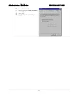
To configure remote client terminals with MS Windows XP operating system
1
Click on ‘
Start
’
2
Select ‘
Control panel’
Содержание MCM-4
Страница 25: ...G l o b a l s t a r M C M 4 e D R A W I N G S 2 ANCT0601 021 MCM 4e Parts List ...
Страница 26: ...G l o b a l s t a r M C M 4 e D R A W I N G S 3 ANCT0601 021 MCM 4e Front and Rear Panel ...
Страница 27: ...G l o b a l s t a r M C M 4 e D R A W I N G S 4 ANCT0601 021 MCM 4e Top and Side View ...
Страница 28: ...G l o b a l s t a r M C M 4 e D R A W I N G S 5 ANCT0601 021 MCM 4e Top View Cover Removed ...
Страница 31: ...G l o b a l s t a r M C M 4 e D R A W I N G S 8 ANCT0601 021 MCM 4e Cable Diagram ePipe to Switch CCA ...
Страница 32: ...G l o b a l s t a r M C M 4 e D R A W I N G S 9 ANCT0601 021 MCM 4e RF Cable Diagram ...
Страница 33: ...G l o b a l s t a r M C M 4 e D R A W I N G S 10 ANCT0601 021 MCM 4e Chassis and Power Supply Wiring Diagram ...
Страница 34: ...G l o b a l s t a r M C M 4 e D R A W I N G S 11 ANCT0601 029 MCM 4e External RF Cable Drawing ...
Страница 35: ...G l o b a l s t a r M C M 4 e D R A W I N G S 12 ANCT0601 030 MCM 4e Antenna Power Cable Drawing ...
Страница 36: ...G l o b a l s t a r M C M 4 e D R A W I N G S 13 ANCT0601 030 MCM 4e Antenna Power Cable Drawing ...


