background image

Содержание ZZ 2560 Series

Страница 1: ...ZZ 2560 series Flatbed zig zag machines Instruction manual parts book Always switch off the electricity when working on the machine GLOBAL ...

Страница 2: ...zag stitch width 11 24 Needle stab position setting in feeding direction 11 25 Lateral setting of needle stab position 12 26 Lateral setting of central straight stitch position 12 27 Lateral setting of straight stitches on throat plate needle hole edges arresting of zigzag stitch setting mechanism 13 28 The gap between hook assembly and needle adjustment 13 29 Bobbin case driver 14 30 The feed dog...

Страница 3: ...th par t number 17 37 Backtacking with solenoid 18 38 Presser foot lift ing 19 39 Bobbin winder 20 40 Thread trimming 20 41 Machine electronic control and drive 21 2 From the library of Superior Sewing Machine Supply LLC www supsew com ...

Страница 4: ...are installed 2 Operating notice Do not operate the machine if the oil tank without full oil The machine adopt semi automatic lubricating mode Do not operate the machine before lubricating Check the rotation direction of pulley when firstly start new machine The pulley should rotate in counterclockwise when viewed from pulley Check the voltage and phase Single or three phase whether is correspondi...

Страница 5: ...ositioning motor without further functions DC motor AC servo positioning motor with reverse run after thread trimming 40kg 30kg max 20mm 265 x 120mm 178 x 476mm max 800W short time at start up 1060 x 550mm To adjust the tension of belt Change the height of motor through turn the tension adjusting nut It is ok if the belt sinks inside with 15mm when pressing the center position of belt surface Lack...

Страница 6: ...rotect the semiconductor parts Power m ust be turned off when incline machine head only or touch needle Must use earth cable with yellow green color to connect motor When check the internal circuit it must turn off the power firstly and then open the front cover It must wait 10 minutes after turn off the power due the high voltage In box It Is very important to release the internal energy Keep mot...

Страница 7: ...hot Maintenance of control box clean dust ofthe connector It will affect accidental operation if there is more dust on the connector Warning Before cleaning and lubricating the machine be sure to switch off all switches and hold your feet away from the machine stand pedal in order to avoid accidental machine start by pedal Wind the bobbin Fix the bobbin 1 on the winder Do the threading according t...

Страница 8: ... needle groove to right maybe can avoid this condition Normally avoid the needle groove face to left X X 0 14 Bobbin fixing and hook threading Attention Danger of injury Switch the main switch off and wait for the motor stopping Tilt the flap 1 grip it and pull the bobbin case 2 out of the hook Put the bobbin 3 in the bobbin case with the thread end 4 oriented according to the picture Draw the thr...

Страница 9: ...5 6 8 9 The tension of the upper and the lower thread must be interrelated that the stitch forming and the sewn material To adjust the upper threod tension according to the lower thread tension Tum the tension adjusti g nut n doci wlse to Increase the tension o 1wer1ely to decrea It To adjust the lower thread tension by turning adjusting screw A It can adjust the take up spring to adjust upper thr...

Страница 10: ...ng even at the top speed 19 Stitch length setting mechanism Regulation If the zero stitch length is set the hand lever should perform no lost motion Loosen the screws 1 Set the setting knob 2 on the zero stitch length Shift the lever 3 in the arrow direction until its fork is in bilateral contact with the screw spherical end on the knob 2 axis Tighten the screws 1 Check whether the backtacking lev...

Страница 11: ...rection A Setting of zig zag stitch position Press the lever 1 in the arrow direction A until it strikes the lever 2 the lever arrest is released 3 Make sure that the lever setting does not change at the arrest switching off 2 Press the lever 3 and turn it at the same time up to the stop inside the machine against the respective symbol indicating the zig zag stitch position Only the middle positio...

Страница 12: ...c bolt 2 position with the smallest tooth clearance is found Locate the bolt 2 in this position and fix it with a screw 1 22 Straight stitch alignment The centrally positioned straight stitch must be fully aligned i e the needle must not have any lateral motion Set the zero stitch length Loosen the screw 1 Place the stop pin 2 to the stop onto the casing 3 Place a piece of paper onto the throat pl...

Страница 13: ...istance of the holes complies with the regulation Shift the screw 1 to the stop and tighten it 24 Needle stab position setting in feeding direction 2 If the needle is in the bottom dead center it should be positioned in the throat plate needle hole center in feeding direction and its lost motion in the feeding direction should be as small as possible Place the needle in the bottom dead center Loos...

Страница 14: ...dead centers as per regulation Tighten both screws properly 3 Lateral setting of central straight stitch position 3 2 If the central straight stitch is set the needle position should be L approximately in the center of the presser foot or in the middle of the throat plate needle hole center Set the zero width of the zigzag stitch with the lever 1 Loosen the screws 2 Shift the lever 3 until the nee...

Страница 15: ... 5 and turn the lever 2 to the position in which the needle performs no side motion when moving the lever 3 Locate the stop 6 to the lever 2 and fix it with the screw 5 Adjust the arresting lever 7 in this position Tighten the arresting 28 nut 8 invisible loosen the screw 9 turn the lever 7 to 1mm space from the casing 10 and lighten the screw 9 If the sewing equipment does not allow using the max...

Страница 16: ... material To adjust it turn pulley Wheel to the highest position of feed dog loosen the screw 2 of the lifting lever 8 on the shaft 6 adjust it to the required height of the feed dog and retighten the screw 3 A 1 8 3 2 31 The feed dog obliquity adjustment see above picture 6 The standard position of feed dog is horizontal It can be adjusted according to sewn material To adjust it loosen the screw ...

Страница 17: ... adjustment see above picture Adjust the fo ward backward stitch length error through to adjust the position of the backstitch block on backstitch connection shaft Lean the machine head backward loosen backstitch block screw 1 At same time press backstitch pin 3 of backstitch connection shaft 2 in order to avoid it fall off backstitch control lever crank 4 Bac Jtch length win be increased when rem...

Страница 18: ...s 2 Mount the regulating ring 4 on touch with the scroll 3 Check the tooth clearance b Roller bolt position of form stitch steering cam When changing the form stitch width the stitch central axis should remain in its place It should not shift laterally Mount the wheel steering cam of the straight stitch from the machine rear side t Dismantle the cover of the form stitch width setting mechanism Rel...

Страница 19: ...ismantle the top cover Mount any form stitch cam 1 Loosen 4 screws 2 and tum the scroll 3 to the position where the regulation is complied with Put the scroll 3 on touch with the regulating ring 4 and fix it Check whether the needle is without any motion at the time when it is stabbed in the sewn material and adjust the setting if needed 36 Form stitch of patterns cam with part number NO OF STITCH...

Страница 20: ...pproximately 1mm Tighten the screw 1 2 Test whether its movable core does not strike the fixed one when the solenoid is switched on 38 Presser foot lifting A Manual foot lifting Regulation The foot stroke with the hand lever should be 5 5mm Place the bottom feed dog under the level of the throat plate top surface Place an object ofthickness 5 5mm under the foot Loosen the screw 1 lift the hand lev...

Страница 21: ... Regulation The foot stroke with the solenoid is 12mm If the foot is lifted the solenoid movable core should be at the stop onto the fixed core Place the foot onto the throat plate Unscrew the solenoid 1 nut Loosen the screw 2 2 5 6 7 Turn the lever 3 with the roller 4 almost on touch with the side and tighten the screw 2 Remove the solenoid core 5 Loosen the screw 6 and try to turn the screw 7 to...

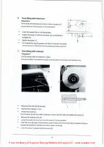
Страница 22: ...4 to the left up to the stop Afterwards shift it by 0 5mm to the right and tighten the screw Then tighten also the other belt pulley fixing screw Adjust the switch lever with the screw 5 and test whether the adjustment complies with the regulation 40 Thread trimming A Trimming pressure between knives Regulation The trimming pressure should be as large as possible however the knives should be on to...

Страница 23: ...hould be positioned as high as possible Tighten the screw 3 Loosen the screw 1 Turn the eccentric bolt 2 so that its groove is almost horizontally positioned Tighten the screw 1 C Driver Regulation 1 2 If the driver 1 touches the casing 2 the knife 3 should be on the plate edge 4 4 3 lI Tilt the machine Loosen the screw 5 Shift the knife 3 as per regulation Place the driver 1 on touch with the cas...

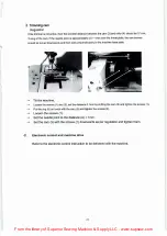
Страница 24: ...plate Tilt the machine Loosen the screws 1 and 2 set the distance 0 1 mm by shifting the cam 3 and tighten the screws 1 Put the ring 5 on touch with the cam 3 and tighten the screws 2 Loosen the screws 1 Set the needle point to the distance A 1mm Set the cam 3 with the screws 1 downwards as per regulation and tighten them Electronic control and machine drive Refer to the electronic control instruc...

Страница 25: ... bar vibrating parts 10 E Needle bar vibrating parts 12 F Presser foot parts 14 G Stitch length adjustment and backstitch parts 16 H Lower shaft feed dog and presser foot lifting parts 18 I Hook assembly _ 20 J Hook assembly Small hook 22 K Thread trimming parts 24 L Tension release electrocircuit board oil circuit parts 26 M Accessories 2s 1 ...

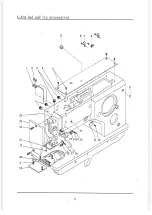
Страница 26: ... Plastic plug 2 2 A10 7 02 1 5 393 Round cover screw 1 1 M3x12 A11 7 02 11 063 Round cover 1 1 A12 7 02 15 392 Thread guide plate screw 1 1 M3x6 A13 7 02 18 070 Screw washer 1 1 GB T97 1 3 A14 7 02 14 028 Thread guide plate 1 1 A15 7 02 14 027 Thread guide plate 1 1 A16 7 02 14 025 Thread guide lever lower 1 1 A17 7 02 15 390 Lower thread guide plate screw 1 1 M3x8 A18 7 02 14 026 Lower thread gui...

Страница 27: ...A Arm bed and its accessories 24 23 22 21 17 20 2 19 3 4 5 2 3 ...

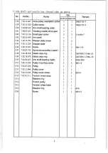
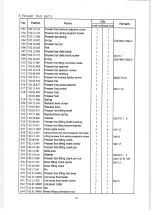
Страница 28: ... 10 Stopper link 1 1 7 11 Spring 1 1 7 12 Connecting seat 1 I 7 13 Washer I 1 1 5 I 1Ox0 3 7 14 Washer 1 1 1 5 4 I lOx1 7 15 Bushing 1 1 7 16 Retainer ring 1 1 GBff896 86 5 1 3 7 17 Stopper block 1 1 7 18 Screw 1 1 M5x6 7 19 Rubber ring I I 7 20 Rubber ring seat I 1 7 21 Screw 1 1 M5x6 7 22 Thread winder and tension bracket base 1 1 B08 7 02 15 1087 Thread winder mounting screw 2 2 M4xl2 B09 7 02 ...

Страница 29: ...B Brbbin winder and thread tension parts 7 2 I 1 e 2 12 13 El 5 ...

Страница 30: ... 1 1 I 2x25mm C18 7 02 05 065 Needle bar connection holder 1 1 C19 7 02 15 056 Needle bar connection bracket tighten screw 1 1 M5x5 C20 7 02 15 400 Needle bar connection bracket screw back 1 1 M4xl2 C21 7 02 15 401 Needle bar connection bracket screw left 1 1 M6 0 75 x30 C22 7 02 15 037 Needle bar connection bracket shaft screw 1 1 M3x6 C23 7 02 15 404 Needle bar connection bracket screw front 1 1...

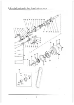
Страница 31: ...C Arm shaft and needle bar thread take up pa r ts 11 12 13 l 11 14 15 1 16 55 I f t i f t _ t 1 i ti 7 39 33 48 l I I I I I I I I I 54 ...

Страница 32: ...screw 2 2 C45 7 02 11 224 Stopper plate 1 1 C46 7 02 15 057 Screw 2 2 M6xlx8 C47 7 02 07 195 Synchronous pulley upper 1 1 C48 7 02 18 076 Elastic stop ring 1 1 GBff893 1 1986 62 C49 7 02 18 078 Elastic stop ring 1 1 GBff894 1 1986 30 C50 7 02 04 027 Arm shaft bearing right 1 1 6206 2RS C51 7 02 15 399 Pulley mounting screw 2 2 M6xl4 C52 7 02 07 054 Pulley 1 1 C53 7 02 11 064 Pulley cover 1 1 C54 7...

Страница 33: ...C Arm shaft and needle bar thread take up parts 11 12 27 28 29 13 1 14 15 1 16 55 I56 45 22 2 47 46 9 48 52 49 50 53 _ I I I I I I I I I Y 54 51 ...

Страница 34: ...shaft 1 1 D1 7 7 02 16 059 Oil spite 2 2 D18 7 02 10 093 Connection shaft 1 1 D19 7 02 05 076 Link lever 1 1 D20 7 02 15 428 Collar screw 2 2 M6 0 75 x5 D21 7 02 09 030 Needle feeding crank shaft collar 1 1 D22 7 02 16 067 Coppery oil spite 1 1 D23 7 02 04 026 Bearing 1 1 51101 D24 7 02 16 064 Aluminium oil plug 1 1 D25 7 02 07 050 Vibrating needle driven gear 1 1 D26 7 02 06 092 Vibrating needle ...

Страница 35: ...D N eedle bar vibrating parts 4 6 7 17 24 o 30 r j I I I I I I I I I I t L ___ _ _J 25 26 27 28 29 I I I 12 13 14 15 16 11 31 37 ...

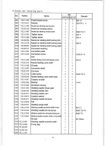
Страница 36: ...E l5 7 02 12 082 Slide block I 1 E16 7 02 16 509 Adjusting plug 1 1 E l 7 7 02 17 480 Spring 1 1 E18 7 02 15 423 Adjusting screw 1 I E19 7 02 18 400 Washer 1 1 E20 7 02 15 1084 Nut 1 1 E21 7 02 08 361 Stopper spanner handle bushin 1 1 E22 7 02 05 510 Stopper spanner I 1 E23 7 02 18 057 Washer 1 1 E24 7 02 15 552 Screw 1 1 M4x20 E25 7 02 15 026 Screw 2 2 M4x6 E26 7 02 11 591 Clamp plate Cleft 1 1 E...

Страница 37: ... parts b r vibrating E Needle a 1 2 3 15 16j 17 I 18 e e l I I I 23 24_J 1 11 36 r1 I I 31 32 13 ...

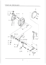
Страница 38: ...se lever screw 1 1 F21 7 02 05 063 Release lever 1 1 F22 7 02 03 073 Presser foot lifting shaft 1 1 F23 7 02 17 086 Replacement spring 1 1 F24 7 02 18 060 Washer 1 1 GB T97 1 8 F25 7 02 08 040 Presser foot lifting shaft bushing 1 1 F26 7 02 19 041 Presser foot lifting electromagnetic 1 1 F27 7 02 15 1085 Fixed plate screw 4 4 M5xJ2 F28 7_021 L095 Lifting presser foot electromagnetic fixed plate 1 ...

Страница 39: ...F Presser foot parts 1____ 2 13 14 151 1 1 15_ ____ 17 18 1 9 26 27 28 29 22 23 24 25 15 31 32 34 35 36 37 8 r 39 __40 _c 41 42 a 43 44 ...

Страница 40: ... 7 02 03 492 Stitch length shaft 1 1 G19 7 02 01 212 Stitch length adjustment assy 1 1 G20 7 02 18 017 Washer 1 1 G21 7 02 15 1086 Screw 1 1 M5x20 G22 7 02 15 1074 Screw 1 1 G23 7 02 18 042 Washer 1 1 G24 7 02 15 574 Nut 1 1 025 7 02 12 050 Backstitch block 1 1 G26 7 02 15 424 Backstitch block screw 1 1 M4x12 G27 7 02 17 092 Replacement spring 1 1 G28 7 02 03 076 Backsitch conneqtion shaft 1 1 G29...

Страница 41: ...G Stitch length d backstitc_hhJP a r ts adjustment an 1 10 6 5 I I 16 15 31 17 ...

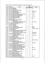
Страница 42: ... 082 Lifting feed dog cam link lever 1 1 H25 Lifting feed dog cam link lever oil wick I I I 2x350mm H26 7 02 15 050 Lifting feed dog cam screw 2 2 M6 0 75 xS H27 7 02 07 055 Lifting feed dog cam 1 I H28 Backstitch cam link lever oil wick 1 I I 2x200mm H29 7 02 10 096 Feed crank pin 2 2 H30 7 02 18 082 Bearing washer 2 2 H31 7 02 04 029 Backstitch cam link lever bearing 1 1 H32 7 02 05 083 Backstit...

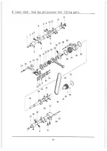
Страница 43: ...H Lower shaft feed dog and presseer foot lifting parts 15 i 1 V 17 44 38 37 6 39 8 9 11 23 24 22 21 I 1 i I 40 j j 41 42 19 13 46 29 I 43 47 29 I 31 30 50 48 32 30 I ...

Страница 44: ...057 Hook gear 1 122 7 02 18 027 Elastic stop ring 1 GBff893 1 1986 22 123 7 02 02 092 Hook 1 124 7 02 21 144 Bobbin 1 125 Bobbin case 1 126 7 02 02 094 Hook orientation claw 1 127 7 02 15 006 Hook orientation claw screw 5 M4x8 128 7 02 02 091 Hook thread distributing claw 1 129 7 02 10 099 Hoo thread distributing bracket 1 DO 7 02 08 110 Hook thread distributing bracket bushing I 131 7 02 15 440 B...

Страница 45: ...I Hook assembly 14 15 16 17 13 11 35 36 37 38 39 40 45 46 21 ...

Страница 46: ...gear 1 122 7 02 18 167 Elastic stop ring 1 GB T893 1 1986 24 123 7 02 02 1 11 Hook 1 124 7 02 21 239 Bobbin 1 125 7 02 02 112 Bobbin case l 126 7 02 02 113 Hook orientation claw l 127 7 02 15 006 Hook orientation claw screw 5 M4x8 128 7 02 02 114 Hook thread distributing claw l 129 7 02 10 099 Hook thread distributing bracket 1 130 7 02 08 110 Hook thread distributing bracket bushing l 131 7 02 15...

Страница 47: ...J Hook asse_ mbly small hook 15 16 17 24 25 26 27 f I 30 29 28 27 39 40 45 46 23 ...

Страница 48: ...I ll J 80 683067 s _ _ s S080 680023 S080 683083 S080 677036 S080 681023 0992 016580 S98 sq8o 683104 I S080 690045 5 S080 683052 i S080 690029 S080 683053 S080 683063 G ...

Страница 49: ...S980 008253 S980 081160 S080 683067 I _ S080 683067 S080 677034 S080 681029 S980 081122 S080 683104 I S080 690045 soso 683052 S080 690029 S080 683053 S080 683063 ...

Страница 50: ...g screw 3 M5xl2 Kl7 7 02 05 515 Thread trimming vibrating lever 1 Kl8 Oil wick 1 M4x8 Kl9 7 02 10 305 Pin 1 K20 7 02 18 402 Washer 1 K21 7 02 21 085 E ring 1 1 9 K22 7 02 15 555 Screw 1 M4x8 K23 7 02 05 514 Thread trimming link lever 1 K24 7 02 10 306 Eccentric pin 1 K25 7 02 18 021 E ring 2 1 7 K26 7 02 08 365 Thread trimming link lever bushing 1 K27 7 02 18 071 Washer 1 K28 7 02 15 577 Screw 1 M...

Страница 51: ...K Thread t rimming parts 14 I 2 3 I 8 M i I I I j i 9 I 1i 1 j 10 I I 11 I o 12 13 33 26 27 28 I 23 25 j 24 25 43 42 36 34 ...

Страница 52: ...2 2 M3x6 L18 Oil wick 1 1 I 2xl50mm L19 Oil tube 1 1 I 3 I 5x70mm L20 7 02 16 032 Felt 2 2 I l6xl2 L21 Oil wick 1 1 I 3x200mm L22 Oil tube 1 1 I 3 I 5xl 10mm L23 7 02 16 034 Felt 1 1 L24 Oil wick 1 1 I 2x250mm L25 Oil tube 1 1 I 3 I 5x300mm L26 Oil tube 1 1 I 3 I 5x200mm L27 Oil wick I 1 I 2x300mm L28 7 02 16 092 Felt 1 1 L29 Oil wick 1 I I 2xl 60mm L30 Oil tube 1 1 I 3 I 5x100mm L31 Oil wick 1 1 ...

Страница 53: ...L Tensiori release electrocircuit board oil circuit parts 5 6 1 7 j 46 11 27 i 47 ...

Страница 54: ...5 445 Screw 4 M6X25 M10 7 02 19 401 Motor 1 M11 7 02 1 5 056 Setscrew 2 M5X5 M12 7 02 07 320 Handwheel bushing 1 M13 7 02 07 321 Handwheel 1 M14 7 02 15 006 Screw 3 M4X8 M15 7 02 03 510 Upper shaft 1 M16 7 02 16 520 Switch pad 1 M17 7 02 16 523 Rear cover 1 M18 7 02 15 974 Screw 2 M5X55 M19 7 02 15 731 Screw 2 M20 7 02 19 400 Eiectric control board 1 M21 7 02 16 522 Plug 2 M22 7 02 15 405 Screw 2 ...

Страница 55: ...M Automatic drive parts 1 24 13 12 11 23 29 14 15 _ 17 18 20 ...

Страница 56: ...18 077 Rubber pad 3 3 N18 17 02 21 13601 Belt cover 1 1 N19 7 02 15 444 Belt cover screw 3 3 M6xl0 N20 7 02 21 138 Nut 2 2 MS N21 7 02 21 137 Screw 1 I N22 1 02 z1 139 Spring washer 1 l GB f93 5 N23 7 02 21 095 Belt 1 1 N24 7 02 21 050 Thread stand l l N25 17 02 21 16401 Oil reservior 1 l N26 7 02 21 157 Wooden screw 9 9 N27 7 02 21 159 Touch block assy I l 27 1 7 02 21 551 Screw l 1 27 2 7 02 21 ...

Страница 57: ...2 j 4 5 6_ a 12 13 fB 14 36 fL J I I 27 i I 21 2 I 30 35 j i _ 27 3 1 i 7 4 33 27 34 i l 28 I I I 31 15 16 l t I 1 2 I J u ...

Страница 58: ...Zig zag cam parts 2 3 4 6 I ll ci2 ...

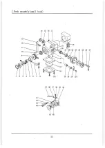
Страница 59: ...ng ring 2 13 7 02 08 117 Worm wheel shaft bushing 1 14 7 02 09 034 Retaining ring 1 15 7 02 15 428 Screw 6 M6 0 75 x5 16 7 02 07 070 Worm bolt 1 17 7 02 10 131 Vibrating needle shaft 1 18 7 02 10 132 Pin roller shaft 1 19 7 02 12 080 Pin roller 1 20 7 02 08 093 Pin roller shaft eccentric bushing 1 21 7 02 01 037 Vibrating needle crank assy 1 22 7 02 15 380 Screw 1 M6X18 23 7 02 08 092 Vibrating li...

Отзывы: