20
•
MEMORY mode detects single shot events and holds indication until
Pulse/Mem switch is toggled.
•
The TTL or CMOS input switching levels can be selected by pressing
button TTL/CMOS.
•
The High and Low thresholds for CMOS depend on the positive voltage
set in the DC Power supplies module. A Logic High level will be detected
when the inputs are 2.0V or higher when TTL is selected, or 70% of the
+V voltage or higher when CMOS is selected. A Logic Low level will be
detected when inputs are 0.8V or less when TTL is selected, or 30% of the
+V voltage or less when CMOS is selected.
•
If CMOS input is selected, the Logic probe module will not work if +V
voltage is less then 1V. In this case the CMOS led will flash.
6.10 Seven segment displays
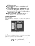
Front-panel controls
Figure 14
shows the Hex to 7 segment LED display module on the front panel of
the trainer.
Figure 14
Description
The Hex to 7 segment decoder can display all hexadecimal characters (0-9 and
A-F) on the seven segment display. The Hex to 7 segment decoder uses an 8 bit
input to display the characters on two 7 segment displays.
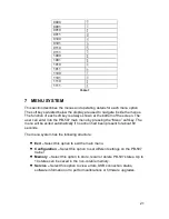
The following table shows the characters displayed on 7 segment display:
Input (S7…S4 or
S3…S0)
7 segment display


