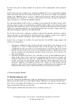
You may also cut the wire, but do not forget to reserve a few centimetres at both sides. The wire-
endings have to be directed into one direction and are not allowed to pass through the hole in the
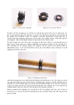
coil-carrier (see fig. 5).
Fig. 5: coil-carrier - completed
Having completed the coil-carrier, you can fix the structure into the core with some
instant glue
.
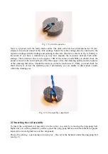
The wire's endings are to leave the core at the closed core-side through a slit (see fig. 6).
Fig. 6: Coil - fixed in the core
At this stage you have to remove the isolation at the wire-endings, starting at one or two
millimetres from the core towards the outside. The optimal tool to remove isolation is a soldering
tool with some fresh solder at the soldering tip. Apply the heated top for some time until the
isolation has been removed and a thin layer of soldering tin is covering the wire. Warning: the
generated smoke may cause damage to your health and should not be inhaled!
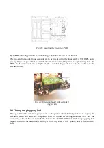
At last you put some instant glue to the backside of the coil and fix the 10nF-capacitor (imprinted
text: 103) in a suitable position to point the wiring connections towards the slit for the coil-
windings. Fig. 7 demonstrates a location for the capacitor besides the carrier's hole – just in case we
may need the hole for some other purpose. The published design however does not really require
this exact position.
Now cut the capacitor's wiring connections to approx. 5 mm, wind the tinned copper wire-endings
around these wiring connections (maybe using a pair of tweezers) and fix the connection by
soldering.
Test Equipment Depot - 800.517.8431 - 99 Washington Street Melrose, MA 02176


