background image

Page | 9  


Global Lift Corp Warranty Information 

The 

Superior

 series lift has a 5 year structural limited warranty. Global Lift Corp warrants to the 

original retail end user only products manufactured by Global Lift Corp, when properly installed in 
accordance to the assembly and installation instructions, and when the equipment is properly 

used 

and maintained, to be free from material defects and workmanship as stated below: 


Warranty starts from date of original purchase 


Metal structure (not including powder coat) Lifetime limited structural warranty  


Actuator and controls 

– 2 years from date of purchase then 2 years prorated 


Actuator and controls 2 

– 3 years 50% coverage (Customer is responsible for 50% of retail 

cost of the component 


Actuator and controls 3 

– 4 years 30% coverage (Customer is responsible for 70% of retail 

cost of the component 


Battery 

– 1 year from date of purchase 

This warranty does not cover damages to 

ANY 

of our lifts due to accident, abuse, negligence, 

misuse, damage by improper use of chemicals, fading, ice damage, fire, rust beyond structural 
damage( does not cover cosmetic rust),  exceeding the weight capacity for model purchased, failure 
to install or to assemble the product in accordance with the installation and assembly instructions, 
normal wear and tear from day to day use, not maintained properly, if unit is altered or repaired 
without written approval of Global Lift Corp 

– All Warranties are Void. 


To commence the warranty claim process of a Global Lift Corp product, in writing provide place of 
purchase along with the product name and description, date of installation and a detailed description 
of the defect, along with a photo of the entire product and claimed defect. Prior to a 30 day period 

Содержание P-375

Страница 1: ...Page 1 GLOBAL LIFT CORP Owner s Manual Proformance Series 684 N Port Crescent Rd Suite C Bad Axe MI 48413 Toll Free 866 712 0606 Fax 989 269 5902 www globalliftcorp com...

Страница 2: ...H CONTROLS PAGE 5 SUPERIOR SERIES OPERATING INSTRUCTIONS PAGE 6 UNIT MAINTENANCE AND CARE PAGE 7 TROUBLESHOOTING PAGE 8 WARRANTY INFORMATION PAGE 9 10 11 WARRANTY REGISTRATION PAGE 12 NEW CONSTRUCTION...

Страница 3: ...cess equipment Global Lift Corp s key staff has a century of combined industry experience and we take pride in each and every product that we build Our Company is ISO Certified and our products are ma...

Страница 4: ...Clear Deck Space On the side of the seat opposite the water a clear deck space shall be provided parallel with the seat The space shall be 36 inches 915 mm wide minimum and shall extend forward 48 in...

Страница 5: ...n the up On position Once unlocked the arrow pointing down will lower the lift when depressed the arrow that points up will raise the unit when depressed If you hear the low battery indicator tone Do...

Страница 6: ...he cycle you can stop the lift whenever you deem comfortable to exit the lift However when exiting the pool while on the lift you should complete the cycle back to the top to have a completely safe ex...

Страница 7: ...er lift after use Weekly o Overview Daily Checklist o Wipe away any surface rust with household spray cleaner o Clean tough stains with Scotchbrite pad and wipe clean Monthly o Inspects all connection...

Страница 8: ...handset and actuator plugs are fully inserted d Check the cables for damage e Check to see if the battery has 24 volts using a multimeter or volt meter f Listen for relay clicking in the control unit...

Страница 9: ...years 30 coverage Customer is responsible for 70 of retail cost of the component Battery 1 year from date of purchase This warranty does not cover damages to ANY of our lifts due to accident abuse neg...

Страница 10: ...rized to make any other specific or implied warranties on behalf of Global Lift Corp THE WARRANTIES ARE IN LIEU OF ALL OTHER WARRANTIES EXPRESSED OR IMPLIED WHICH ARE HEREBY DISCLAIMED AND EXCLUDED IN...

Страница 11: ...which originated the sale or directly to Global Lift Corporation Global Lift Corporation shall determine warranty coverage validation and replacement parts or repair which were directed to the distri...

Страница 12: ...______________ State _______________ Zip ___________ Phone _____ ______________________________ Model __________________________ Serial Number ____________________ Color _______________ Purchase Price...

Страница 13: ...PERFORMANCE SERIES LIFT NEW CONSTRUCTION SAW CUT SLEEVE ANCHORING METHOD INSTALLATION MANUAL FEB 2015 Performance New Construction Saw Cut Anchor...

Страница 14: ...PERFORMANCE SERIES SLEEVE ANCHORING SYSTEM INSTALLATION PARTS LIST 1 Anchor Sleeve w Base 1 Binding screw 1 Plastic Cap FEB 2015 Performance New Construction Saw Cut Anchor...

Страница 15: ...ANCHORING SLEEVE BASE PLATE BINDING SCREW Performance Series FEB 2015 Performance New Construction Saw Cut Anchor...

Страница 16: ...he seat and the pool edge shall have a slope not steeper than 1 48 Clear Deck Space On the side of the seat opposite the water a clear deck space shall be provided parallel with the seat The space sha...

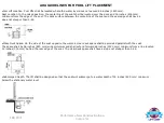
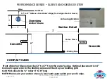
Страница 17: ...NOTE Make sure your anchor sleeve is level and square with your pool s edge COMPACT SAND 6 3 Concrete Concrete Cold Pin Cold Pin Water Pool Wall 3 3 Anchor Sleeve Overview Section Detail 12 to 17 Dis...

Страница 18: ...determined location for installation chalk out a 3 X 3 area prior to cutting out the concrete Refer to overview the front end of the Anchor Sleeve must be 12 to 17 from the water s edge and 6 deep Ne...

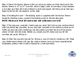
Страница 19: ...al codes and ordinances are met Step 7 Pouring your concrete make sure you cover the hole on your anchor sleeve with the plastic cap provided so you don t get concrete in the sleeve a minimum of 4 000...

Страница 20: ...PERFORMANCE SERIES LIFT RETRO FIT SLEEVE ANCHORING METHOD INSTALLATION MANUAL S P Retro Fit Sleeve Anchoring Method...

Страница 21: ...RETRO FIT SLEEVE ANCHORING SYSTEM PERFORMANCE SERIES LIFT PACKING LIST 1 Anchor Sleeve w Base 1 Binding Screw 1 Plastic Cap S P Retro Fit Sleeve Anchoring Method...

Страница 22: ...a slope not steeper than 1 48 Clear Deck Space On the side of the seat opposite the water a clear deck space shall be provided parallel with the seat The space shall be 36 inches 915 mm wide minimum...

Страница 23: ...NOTE From the water s edge to the front end of the Anchor sleeve must 12 to 17 See picture B Picture A Picture B Front Edge of Anchor Sleeve Water s edge Must be 12 to 17 in distance from the front o...

Страница 24: ...above Also Double check your measurements they should be Place your anchor sleeve in the hole and make sure the front edge of the sleeve is 12 to 17 from the pools edge Along with connecting to the bo...

Страница 25: ...tore in your area Read the label and follow manufacturer s instructions Start pouring into the hole evenly until you fill it up make sure not to overfill the hole so that it does not create more work...

Страница 26: ...nchor Performance Series Once you have completed the installation of your lift locate the 3 8 bolt and secure it in the pre drilled hole inside the anchor sleeve and tighten Your lift is now ready to...

Страница 27: ...cation to be drilled After drilling your hole it must be 2 1 2 deep Clean hole with pressurized air or vacuum Administer Epoxy into the hole prior to inserting the drop in anchor Drive the anchor flus...

Страница 28: ...GLOBAL LIFT CORP CUSTOM SEAT INSTALLATION MANUAL C P S Series Lifts...

Страница 29: ...EAT INSTALLATION MANUAL PARTS LIST 1 Custom Seat 1 Foot Rest 2 Arm Rests 1 Seat Belt Buckle 1 x 2 3 4 Securing Bolt 3 5 16 x 3 Attaching Pin with lock nut 1 5 16 x 2 Foot Rest attaching bolt w nut 1 2...

Страница 30: ...INSTALLATION STEPS Step 1 Unpack your custom seat picture A Loose Items will consist of Foot Rest and Tube x 3 Bolt w lock nut 5 16 x 2 Bolt with Lock nut Picture A...

Страница 31: ...ower seat tube into the upper Seat tube Step 3 Once you have the seat in place take your x 3 bolt and slide it through the pre drilled Holes Picture B Once you have inserted the bolt all the way throu...

Страница 32: ...Locate the 5 16 x 3 securing bolt supplied insert the bolt through the pre drilled Seat and tube holes As shown Above Once you have the bolt inserted secure the installation With the lock nut that is...

Страница 33: ...holes to choose from depending on your preference for the height of the footrest In picture B locate the 5 16 x 2 bolt and insert into the pre drilled holes to secure the foot rest to the lift Place...

Страница 34: ......

Страница 35: ......

Страница 36: ......

Страница 37: ......

Страница 38: ......

Страница 39: ......

Отзывы: