background image


2807940 uATX Motherboard


Page 54 

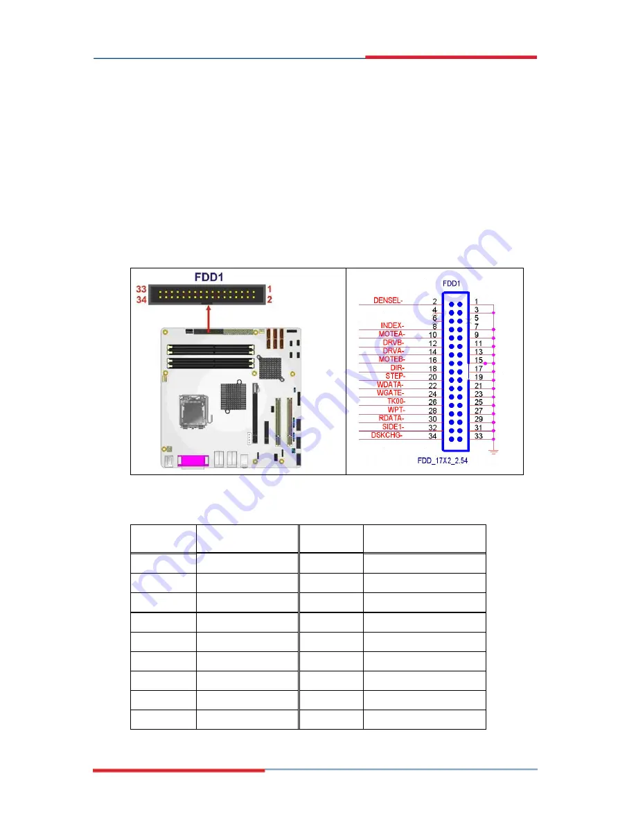
4.2.7 Floppy Disk Connector (34-pin) 

CN Label: 

FDD1 

CN Type: 

34-pin header (2x17) 

CN Location: 

See 

Figure 4-8


CN Pinouts: 

See 

Table 4-9


The floppy disk connector is connected to a floppy disk drive. 


Figure 4-8: 34-pin FDD Connector Location 


PIN NO. 

DESCRIPTION 

PIN NO. 

DESCRIPTION 

1 GND 

2 Density 

Select# 

3 GND 

4 N/C 

5 N/C 

6 N/C 

7 GND 

8 INDEX# 

9 GND 

10 

MOTOR 

ENABLE 

A# 

11 

GND 

12 

DRIVE ENABLE B# 

13 GND 

14 DRIVE 

ENABLE 

A# 

15 

GND 

16 

MOTOR ENABLE B# 

17 GND 

18 DIRECTION# 

Содержание 2807940

Страница 1: ...x x 2807940 User s Manual Micro ATX Motherboard with LGA 775 Socket Version 1 0 ...

Страница 2: ...ssibility of such damages The manufacturer keeps the rights in the subject to change the contents of this document without prior notices in order to improve the function design performance quality and reliability The author assumes no responsibility for any errors or omissions which may appear in this document nor does it make a commitment to update the information contained herein Trademarks Inte...

Страница 3: ...ge A warning message is shown below WARNING This is an example of a warning message Failure to adhere to warning messages may result in permanent damage to the 2807940 or personal injury to the user Please take warning messages seriously CAUTION Cautionary messages should also be heeded to help reduce the chance of losing data or damaging the 2807940 Cautions are easy to recognize The word caution...

Страница 4: ...information These messages should be read carefully as any directions or instructions contained therein can help avoid making mistakes Notes are easy to recognize The word note is written as NOTE both capitalized and bold and is followed by text The text is the cautionary message A note message is shown below NOTE This is an example of a note message Notes should always be read Notes contain criti...

Страница 5: ...Global American Inc at 800 833 8999 or link to Technical Support The items listed below should all be included in the 2807940 package 1 x 2807940 single board computer 3 x SATA power cables 6 x SATA cables 1 x Dual RS 232 cable 1 x USB cable 1 x Mini jumper pack 1 x Utility CD 1 x IO shielding 1 x QIG quick installation guide Images of the above items are shown in Chapter 3 ...

Страница 6: ...field Processors 12 2 3 3 Supported Intel Core 2 Duo Wolfdale Processors 13 2 3 4 Supported Intel Core 2 Duo Conroe Processors 13 2 3 5 Supported Intel Celeron Conroe Processors 14 2 4 INTEL Q35 NORTHBRIDGE CHIPSET 14 2 4 1 Intel Q35 Northbridge Chipset 14 2 4 2 Intel Q35 Front Side Bus FSB Support 14 2 4 3 Intel Q35 Memory Controller 15 2 4 4 Intel Q35 PCIe x16 Interface 16 2 4 5 Intel Q35 Graphi...

Страница 7: ...e Bus Overview 26 2 6 2 PCIe x16 Slot 27 2 6 3 PCIe x4 Slot 27 2 6 4 Intel 82573L PCIe GbE Controller 28 2 7 PCI BUS COMPONENTS 29 2 7 1 PCI Bus Overview 29 2 7 2 PCI Slots 29 2 8 LPC BUS COMPONENTS 30 2 8 1 LPC Bus Overview 30 2 8 2 TPM Module 30 2 8 3 Super I O chipset 31 2 8 3 1 Super I O LPC Interface 33 2 8 3 2 Super I O 16C550 UARTs 33 2 8 3 3 Super I O Enhanced Hardware Monitor 33 2 8 3 4 S...

Страница 8: ... Connectors 45 4 1 3 External Interface Panel Connectors 46 4 2 INTERNAL PERIPHERAL CONNECTORS 47 4 2 1 ATX Power Connector 47 4 2 2 Audio CD In Connector 49 4 2 3 CPU Power Connector 50 4 2 4 Digital Input Output DIO Connector 50 4 2 5 Fan Connector CPU 12V 4 pin 52 4 2 6 Fan Connector System 12V 3 pin 53 4 2 7 Floppy Disk Connector 34 pin 54 4 2 8 Front Audio Connector 55 4 2 9 Front Panel Conne...

Страница 9: ...tion 77 5 4 2 Socket LGA775 2107695 Cooling Kit Installation 80 5 4 3 DIMM Installation 82 5 4 3 1 DIMM Purchasing Guidelines 83 5 4 3 2 DIMM Installation Order 83 5 4 3 3 DIMM Installation Guidelines 84 5 5 JUMPER SETTINGS 85 5 5 1 Clear CMOS Jumper 86 5 5 2 COM Port Pin 9 Setting Jumpers 87 5 5 3 COM Port Pin 9 Voltage Setting Jumpers 89 5 6 CHASSIS INSTALLATION 90 5 6 1 Airflow 90 5 6 2 Motherb...

Страница 10: ... A TERMINOLOGY 114 B DIO INTERFACE 119 B 1 DIO INTERFACE INTRODUCTION 120 B 2 DIO CONNECTOR PINOUTS 120 B 3 ASSEMBLY LANGUAGE SAMPLES 121 B 3 1 Enable the DIO Input Function 121 B 3 2 Enable the DIO Output Function 121 C WATCHDOG TIMER 122 D ADDRESS MAPPING 125 D 1 ADDRESS MAP 126 D 2 1ST MB MEMORY ADDRESS MAP 126 D 3 IRQ MAPPING TABLE 127 D 4 DMA CHANNEL ASSIGNMENTS 127 E COMPATIBILITY 128 E 1 CO...

Страница 11: ...reating a RAID Volume 134 F 4 2 Deleting a RAID Volume 139 F 4 3 Resetting a Disk to Non RAID 141 F 4 4 Exiting the Matrix Storage Manager 143 G HAZARDOUS MATERIALS DISCLOSURE 145 G 1 HAZARDOUS MATERIAL DISCLOSURE TABLE FOR IPB PRODUCTS CERTIFIED AS ROHS COMPLIANT UNDER 2002 95 EC WITHOUT MERCURY 146 H INDEX 148 ...

Страница 12: ...M Gigabit LAN Connect Device 22 Figure 2 10 SATA Drive Connectors 25 Figure 2 11 Onboard USB Implementation 26 Figure 2 12 PCIe x16 Slot 27 Figure 2 13 PCIe x4 Slot 28 Figure 2 14 Intel 82573L PCIe GbE Controller 28 Figure 2 15 PCI Slots 30 Figure 2 16 TPM Connector 31 Figure 2 17 ITE IT8712F Super I O 32 Figure 2 18 LAN Connections 36 Figure 4 1 Connector and Jumper Locations 44 Figure 4 2 ATX Po...

Страница 13: ...4 21 RJ 45 Ethernet Connector 68 Figure 4 22 Parallel Port Connector Pinout Locations 69 Figure 4 23 COM1 Pinout Locations 70 Figure 4 24 VGA Connector 71 Figure 5 1 Intel LGA775 Socket 77 Figure 5 2 Remove the CPU Socket Protective Shield 78 Figure 5 3 Open the CPU Socket Load Plate 79 Figure 5 4 Insert the Socket LGA775 CPU 80 Figure 5 5 GAI 2107695 Cooling Kit 81 Figure 5 6 Securing the Heat si...

Страница 14: ... VGA Connector 103 Figure 8 1 Intel Active Management Technology Status Dialog 105 Figure 8 2 Intel Current ME Password 107 Figure 8 3 Change Intel ME Password 107 Figure 8 4 Verify New Password 108 Figure 8 5 Intel AMT Configuration 108 Figure 8 6 Provision Model 108 Figure 8 7 Intel AMT 3 0 Mode 109 Figure 8 8 Enterprise 109 Figure 8 9 Enable Network Interface 110 Figure 8 10 Exit 111 Figure 8 1...

Страница 15: ... Power Connector Pinouts 50 Table 4 6 DIO Connector Pinouts 51 Table 4 7 12V Fan Connector Pinouts 52 Table 4 8 12V Fan Connector Pinouts 53 Table 4 9 34 pin FDD Connector Pinouts 55 Table 4 10 Front Audio Connector Pinouts 56 Table 4 11 Front Panel Connector Pinouts 14 pin 57 Table 4 12 Infrared Connector Pinouts 58 Table 4 13 PCIe Power Connector Pinouts 59 Table 4 14 SATA Drive Connector Pinout...

Страница 16: ...nouts 70 Table 4 24 RS 232 Serial Port COM 1 Pinouts 70 Table 4 25 VGA Connector Pinouts 71 Table 5 1 Jumpers 86 Table 5 2 Clear CMOS Jumper Settings 87 Table 5 3 COM Port Pin 9 Setting Jumper Settings 88 Table 5 4 COM Port Pin 9 Voltage Setting Jumper Settings 89 Table 5 5 GAI Provided Cables 91 ...

Страница 17: ...2807940 uATX Motherboard Page 1 1 Introduction Chapter 1 ...

Страница 18: ... or 800 MHz un buffered DDR2 SDRAM DIMM are supported by the Intel Q35 graphics memory controller hub GMCH The Intel Q35 GMCH also has a single PCI Express x16 PCIe x16 expansion lane for a PCIe x16 graphics card The integrated Intel ICH9DO I O controller hub ICH supports six SATA II drives with data transfer speeds of 3 0 Gbps with SATA RAID configuration support Twelve USB 2 0 channels one expan...

Страница 19: ... 2 GB 667 MHz or 800 MHz DDR2 DIMMs Six SATA II drives with transfer rates of 3 0 Gbps supported Twelve USB 2 0 devices supported eight onboard and four on the rear panel Dual GbE Ethernet connectors uATX form factor RoHS compliant Supports ATX power supplies 1 2 2807940 Overview 1 2 1 2807940 Overview Photo The 2807940 has a wide variety of peripheral interface connectors Figure 1 2 is a labeled ...

Страница 20: ...4 Figure 1 2 2807940 Overview Front View 1 2 2 2807940 Peripheral Connectors and Jumpers The 2807940 has the following connectors on board 1 x ATX power connector 1 x Audio connector 1 x CD in connector 1 x Cooling fan connector CPU ...

Страница 21: ...TA drive connectors 3 x Serial port connectors 1 x SPDIF connector 1 x SPI flash connector 1 x TPM connector 4 x USB connectors support eight USB devices The 2807940 has the following external peripheral interface connectors on the board rear panel 3 x Audio jacks 2 x Keyboard mouse connectors 1 x Parallel port 2 x RJ 45 Ethernet connectors 1 x Serial port 4 x USB 2 0 connectors 1 x VGA connector ...

Страница 22: ...rthbridge Intel Q35 Express Chipset Southbridge Intel ICH9DO Memory Four 240 pin DDR2 DIMM sockets support 2 0 GB 667 MHz or 800 MHz DDR2 DIMMs Super I O ITE IT8712F Rev I Display Analog VGA display through external DB 15 connector BIOS AMI BIOS label SPI EEPROM 4 0 MB Audio RealTek ALC883 codec LAN One Intel 82566DM PHY and Intel ICH9DO MAC One PCIe x1 Intel 82573L MAC and PHY COM Four RS 232 ser...

Страница 23: ...sec through the ITE IT8712F super I O Infrared One IrDA connector through the ITE IT8712F super I O Power Supply ATX power supply TPM Supports TPM v1 2 with 20 pin onboard pin header Fan Connector Three pin system fan pin header Four pin CPU fan pin header Buzzer Yes Power Consumption 3 3V 2 41A 5V 5 71A 12V 3 69A 3Dmark 2001 and 5VSB 0 13A 3 0 GHz E6850 Intel Core 2 Duo CPU with four 2 0 GB 800 M...

Страница 24: ...2807940 uATX Motherboard Page 8 2 Detailed Specifications Chapter 2 ...

Страница 25: ...2807940 uATX Motherboard Page 9 2 1 Dimensions 2 1 1 Board Dimensions The dimensions of the board are listed below Length 243 84mm Width 243 84mm Figure 2 1 2807940 Dimensions mm ...

Страница 26: ...07940 uATX Motherboard Page 10 2 1 2 External Interface Panel Dimensions External peripheral interface connector panel dimensions are shown in Figure 2 2 Figure 2 2 External Interface Panel Dimensions mm ...

Страница 27: ...Page 11 2 2 Data Flow Figure 2 3 shows the data flow between the two on board chipsets and other components installed on the motherboard and described in the following sections of this chapter Figure 2 3 Data Flow Block Diagram ...

Страница 28: ...Supported Intel Core 2 Quad Yorkfield Processors The Yorkfield core Intel Core 2 Quad CPU is a 45nm LGA775 processor NOTE As of the date of writing this manual December 2007 Intel has not released Intel Core 2 Quad Yorkfield processor numbers that are supported by the Intel Northbridge As soon as processor numbers are released the manual will be updated For further details about supported Intel Co...

Страница 29: ...sor numbers are released the manual will be updated For further details about supported Intel Core 2 Duo Wolfdale processors please contact Intel directly 2 3 4 Supported Intel Core 2 Duo Conroe Processors Table 2 1 lists the Conroe core Intel Core 2 Duo processors supported on the 2807940 All the processors in Table 2 1 are 65nm LGA775 processors with the following features Enhanced Halt State C1...

Страница 30: ...eleron Processors 2 4 Intel Q35 Northbridge Chipset 2 4 1 Intel Q35 Northbridge Chipset The Intel Q35 Northbridge chipset is an advanced Graphics and Memory Controller Hub GMCH that supports a range of Intel processors including 45nm Wolfdale dual core and Yorkfield quad core and 65nm Conroe core processors The Intel Q35 Northbridge supports 1333 MHz 1066 MHz or 800 MHz FSB and up to 8 0 GB of 667...

Страница 31: ...e 2 4 Front Side Bus FSB 2 4 3 Intel Q35 Memory Controller The memory controller on the Intel Q35 Northbridge can support up to 8 0 GB of DDR2 SDRAM Four DDR2 SDRAM DIMM sockets on the 2807940 are interfaced to the Intel Q35 Northbridge memory controller The DDR2 sockets are shown in Figure 2 5 Figure 2 5 DDR2 DIMM Sockets ...

Страница 32: ...um capacity per DIMM 8 0 GB supported with four DIMM Memory bandwidth o 6 4 GBps in single channel or dual channel asymmetric mode o 12 8 GBps in dual channel interleaved mode assuming DDR2 800MHz 2 4 4 Intel Q35 PCIe x16 Interface The Intel Q35 PCIe bus is compliant with the PCI Express 1 1a Specifications has the following PCIe lanes One PCIe x16 graphics interface PCIe frequency of 1 25 GHz 2 5...

Страница 33: ...CH integrated graphics device IGD has 3D 2D and video capabilities The Unified Memory Architecture UMA uses up to 256 MB of Dynamic Video Memory Technology DVMT for graphics memory External graphics accelerators on the PCIe graphics PEG port are supported but cannot work simultaneously with the IGD 2 4 6 Intel Q35 Analog Display Capability A single external female DB 15 VGA connector interfaces an...

Страница 34: ...tion bus between the Intel Q35 GMCH and the ICH9DO I O controller hub ICH The DMI is a high speed interface that integrates advanced priority based servicing and allows for concurrent traffic and true isochronous transfer capabilities The DMI is shown in Figure 2 7 Figure 2 7 DMI Chip to Chip Connection Some of the features of the DMI include 2 0 GBps point to point DMI to ICH9DO 1 0 GBps in each ...

Страница 35: ...I slots on the motherboard 2 5 2 Intel ICH9DO Features The ICH9DO Southbridge chipset on the 2807940 has the features listed below Complies with PCI Express Base Specification Revision 1 1 Complies with PCI Local Bus Specification Revision 2 3 and supports 33MHz PCI operations Supports ACPI Power Management Logic Contains o Enhanced DMA controller o Interrupt controller o Timer functions Integrate...

Страница 36: ...ted on the Intel ICH9DO The audio connector is shown in Figure 2 8 Figure 2 8 Audio Connectors 2 5 4 Intel ICH9DO Ethernet Controller NOTE Gigabit Ethernet 1000 Mbps is only supported in S0 The Intel ICH9DO Southbridge integrated GbE controller is interfaced to an Intel 82566DM Gigabit LAN connect device through the Gigabit LAN Connect Interface GLCI and LAN Connect Interface LCI The GLCI is share...

Страница 37: ...3x Flow Control Specification 64 bit address master support for system using more than 4 GB of physical memory Configurable receive and transmit data FIFO programmable in 1 KB increments Intelligent interrupt generation to enhance driver performance Compliance with Advanced Configuration and Power Interface Compliance with PCI Power Management standards ACPI register set and power down functionali...

Страница 38: ...the features of the Intel 82556DM are listed below 10 Mbps 100 Mbps or 1000 Mbps Supports Intel Active Management Technology Supports Intel Virtualization Technology through the Intel Virtual Gigabit Network Connection Can support legacy ASF2 0 Shared SPI flash with system BIOS Integrated linear voltage regulator TCP UDP checksum and segmentation offload Receive side scaling Dual TX and RX queues ...

Страница 39: ...sters are interfaced to the following onboard components Two PCI sockets 2 5 7 Intel ICH9DO PCIe x4 Bus The Intel ICH9DO Southbridge chipset has six PCIe x1 lanes The four PCIe lanes are interfaced to one PCIe x4 slot on the 2807940 motherboard One of the remaining PCIe x1 lanes is connected to an Intel 82566DM GbE controller and the other PCIe x1 lane is connected to an Intel 82573L GbE controlle...

Страница 40: ...upports three modes of operation Native IDE enabled operating system Two controllers enable all six ports on the bus Controller 1 supports Port 0 Port 1 Port 2 and Port 3 Controller 2 supports Ports 4 and Port 5 Legacy operating system is used One controller is enabled and only supports Port 0 Port 1 Port 2 and Port 3 AHCI or RAID mode One controller supports all six ports including Port 0 Port 1 ...

Страница 41: ...lers that support the standard Universal Host Controller Interface UHCI Revision 1 1 Each controller supports two USB devices ensuring up to twelve USB 1 1 devices can be connected to the 2807940 The ICH9DO also comprises two high speed Enhanced Host Controller Interface EHCI controllers Each EHCI controller supports six USB 2 0 devices ensuring twelve USB 2 0 devices can be connected to the 28079...

Страница 42: ... 6 2807940 PCIe Bus Components 2 6 1 PCIe Bus Overview The 2807940 has one PCIe x16 channel from the Intel Q35 Northbridge and six PCIe x1 lanes from the Intel ICH9DO Southbridge The PCIe bus lanes are interfaced to the following devices One PCIe x16 lane is connected to one PCIe x16 graphics card Four PCIe x1 lanes are connected to one PCIe x4 expansion card One PCIe x1 lane are connected to one ...

Страница 43: ... PCIe x16 slot on the 2807940 motherboard The PCIe x16 graphics card is then installed on the PCIe x16 slot on the motherboard The PCIe x16 edge connector is shown in Figure 2 12 Figure 2 12 PCIe x16 Slot 2 6 3 PCIe x4 Slot Four of the six PCIe x1 expansion channels on the 2807940 are interfaced to one PCIe x4 slot on the 2807940 motherboard The PCIe x4 slot is shown in Figure 2 13 ...

Страница 44: ...el ICH9DO Southbridge through a PCIe x1 lane The Intel 82573L GbE controllers is shown in Figure 2 14 below Figure 2 14 Intel 82573L PCIe GbE Controller Some of the features of the Intel 82573L are listed below 2 Gbps peak bandwidth per direction PCI Express Rev 1 0a specification High bandwidth density per pin Wide pipelined internal data path architecture Optimized transmit Tx and receive Rx que...

Страница 45: ...096 VLAN tags Boot ROM Preboot eXecution Environment PXE Flash interface support SDG 3 0 WfM 3 0 and PC2001 compliant Wake on LAN support 2 7 PCI Bus Components 2 7 1 PCI Bus Overview The PCI bus is connected to the components listed below Two PCI slots The PCI bus complies with PCI Local Bus Specification Revision 2 3 and supports 33MHz PCI operations 2 7 2 PCI Slots The Intel ICH9DO Southbridge ...

Страница 46: ...view The LPC bus is connected to components listed below TPM module connector Super I O chipset Fintek F81216DG LPC Serial Port Chipset 2 8 2 TPM Module A TPM connector on the 2807940 is interfaced to the Intel ICH9DO Southbridge through the LPC bus The TPM connector is shown in Figure 2 16 below ...

Страница 47: ... from GAI The three GAI TPM are listed below Infineon TPM module Sinosun TPM module Winbond TPM module For more information about these modules please refer to Chapter 3 or contact the Global American Inc 2 8 3 Super I O chipset The ITE IT8712F Super I O chipset is connected to the Intel ICH9DO Southbridge through the LPC bus ITE IT8712F Super I O chipset is shown in Figure 2 17 below ...

Страница 48: ...features of the ITE IT8712F chipset are listed below PC98 99 2001 ACPI and LANDesk Compliant Enhanced Hardware Monitor Fan Speed Controller Single 5V Power Supply Two 16C550 UARTs for serial port control One IEEE 1284 Parallel Port Keyboard Controller Watchdog Timer Serial IRQ Support Vbat Vcch Support Single 5V Power Supply Some of the Super I O features are described in more detail below ...

Страница 49: ...o another three serial port connectors COM2 COM3 and COM4 For further details on the Fintek F81216DG serial port controller please refer to Section 2 8 4 2 8 3 3 Super I O Enhanced Hardware Monitor The Super I O Enhanced Hardware Monitor monitors three thermal inputs VBAT internally and eight voltage monitor inputs These hardware parameters are reported in the BIOS and can be read from the BIOS Ha...

Страница 50: ...er features are listed below The 8042 instruction is compatible with a PS 2 keyboard and PS 2 mouse Gate A20 and Keyboard reset output Supports multiple keyboard power on events Supports mouse double click and or mouse move power on events 2 8 3 7 Super I O GPIO Ports The Super I O has 48 programmable GPIO ports of which 8 are implemented on the 2807940 The GPIO connector has 8 programmable bits 4...

Страница 51: ...cond with a maximum or either 65 535 minutes or 65 535 seconds 2 8 4 Fintek F81216DG LPC Serial Port Chipset The Fintek F81216DG chipset enables the addition of three additional UART serial ports COM2 COM3 and COM4 UART includes 16 byte send receive FIFO The Fintek serial port chipset is interfaced to the Southbridge chipset through the LPC bus Some of the features of the Fintek chipset are listed...

Страница 52: ...ernet LAN connector through an Intel 82566DM Gigabit Platform LAN Connect device The Intel 82566DM is connected directly to the GbE controller on the Intel ICH9DO Southbridge through the GLCI and LCI which is shared with the PCIe x1 port 6 Both of these Ethernet controllers have been described in detail in earlier sections For further details please refer to the relevant sections Intel ICH9DO Ethe...

Страница 53: ...ardware Monitor monitors the following voltages CPU Core DDR2 1 8V 3 3V 5V 12V FSB 1 2V 1 5V 1 25V VBAT The 2807940 Super I O Enhanced Hardware Monitor also monitors the following fan speeds CPU Fan Speed System Fan Speed The values for the above environmental parameters are all recorded in the BIOS Hardware Health Configuration menu 2 10 2 Operating Temperature and Temperature Control The maximum...

Страница 54: ... CPU Heat sinks are also mounted on the Northbridge and Southbridge chipsets to ensure the operating temperature of these chips remain low 2 10 3 Power Consumption Table 2 3 shows the power consumption parameters for the 2807940 running 3D Mark 2001 SE330 with a 3 0 GHz E6850 Intel Core 2 Duo processor with four 2 0 GB 800MHz DDR2 DIMMs Voltage Current 3 3V 2 41A 5 0V 5 71A 12V 3 69A 5Vsb 0 13A Ta...

Страница 55: ...2807940 uATX Motherboard Page 39 3 Unpacking Chapter 3 ...

Страница 56: ...ic wristband can help to prevent ESD from damaging the board Self grounding Before handling the board touch any grounded conducting material During the time the board is handled frequently touch any conducting materials that are connected to the ground Use an anti static pad When configuring the 2807940 place it on an antic static pad This reduces the possibility of ESD damaging the 2807940 Only h...

Страница 57: ...ecklist below are missing please do not proceed with the installation Contact Global American Inc at 800 833 8999 x x 3 3 1 Package Contents The 2807940 is shipped with the following components Quantity Item and Part Number Image 1 2807940 motherboard 1 Dual RS 232 cable 6 SATA cables 3 SATA power cables ...

Страница 58: ...Pack 1 Quick Installation Guide 1 Utility CD Table 3 1 Package List Contents 3 4 Optional Items CPU cooling kit P N 2107695 Infineon TPM module P N 1007790 Sinosun TPM module P N 1007800 Winbond TPM module P N 1007810 Table 3 2 Package List Contents ...

Страница 59: ...2807940 uATX Motherboard Page 43 4 Connector Pinouts Chapter 4 ...

Страница 60: ...peripheral interface connector locations Section 4 1 2 lists all the peripheral interface connectors seen in Section 4 1 2 4 1 1 2807940 Layout Figure 4 1 shows the on board peripheral connectors rear panel peripheral connectors and on board jumpers Figure 4 1 Connector and Jumper Locations ...

Страница 61: ... pin wafer SYS_FAN1 CPU power connector 4 pin wafer CPU12V1 Digital input output connector 10 pin header DIO1 DIMM socket 240 pin socket DIMM1 DIMM socket 240 pin socket DIMM2 DIMM socket 240 pin socket DIMM3 DIMM socket 240 pin socket DIMM4 Floppy drive connector 34 pin box header FDD1 Front audio connector 10 pin header FP_AUDIO1 Front panel connector 14 pin header F_PANEL1 Infrared IrDA connect...

Страница 62: ...rial port connector COM3 10 pin box header COM3 Serial port connector COM4 10 pin box header COM4 SPDIF connector 5 pin header SPDIF1 SPI flash connector 8 pin header JSPI1 TPM connector 20 pin header TPM1 USB connector 8 pin header USB45 USB connector 8 pin header USB67 USB connector 8 pin header USB89 USB connector 8 pin header USB1011 Table 4 1 Peripheral Interface Connectors 4 1 3 External Int...

Страница 63: ...Table 4 2 Rear Panel Connectors 4 2 Internal Peripheral Connectors Internal peripheral connectors are found on the motherboard and are only accessible when the motherboard is outside of the chassis This section has complete descriptions of all the internal peripheral connectors on the 2807940 4 2 1 ATX Power Connector CN Label ATX1 CN Type 24 pin ATX 2x12 CN Location See Figure 4 2 CN Pinouts See ...

Страница 64: ...or Pinout Locations PIN NO DESCRIPTION PIN NO DESCRIPTION 1 3 3V 13 3 3V 2 3 3V 14 12V 3 GND 15 GND 4 5V 16 PS_ON 5 GND 17 GND 6 5V 18 GND 7 GND 19 GND 8 Power good 20 5V 9 5VSB 21 5V 10 12V 22 5V 11 12V 23 5V 12 3 3V 24 GND Table 4 3 ATX Power Connector Pinouts ...

Страница 65: ...Pinouts See Table 4 4 The 4 pin audio CD in connector is connected to an external audio CD device for the input and output of audio signals from a CD player to the system Figure 4 3 Audio CD In Connector Pinouts 4 pin PIN NO DESCRIPTION 1 CD Signal Left 2 Ground 3 Ground 4 CD Signal Right Table 4 4 Audio CD In Connector Pinouts ...

Страница 66: ...ee Figure 4 4 CN Pinouts See Table 4 5 The 4 pin CPU power connector is connected to an ATX power supply and powers the CPU Figure 4 4 CPU Power Connector Location PIN NO DESCRIPTION 1 GND 2 GND 3 12V 4 12V Table 4 5 CPU Power Connector Pinouts 4 2 4 Digital Input Output DIO Connector CN Label DIO1 CN Type 10 pin header 2x5 ...

Страница 67: ... a Super I O chip The DIO connector pins are user programmable To see details on how to program the DIO chip please refer to Appendix B Figure 4 5 DIO Connector Location PIN NO DESCRIPTION PIN NO DESCRIPTION 1 Ground 2 VCC 3 Output 3 4 Output 2 5 Output 1 6 Output 0 7 Input 3 8 Input 2 9 Input 1 10 Input 0 Table 4 6 DIO Connector Pinouts ...

Страница 68: ...or provides a 12V 500mA current to a CPU cooling fan The connector has a rotation pin to get rotation signals from fans and notify the system so the system BIOS can recognize the fan speed Please note that only specified fans can issue the rotation signals Figure 4 6 12V Fan Connector Location PIN NO DESCRIPTION 1 GND 2 12VCC 3 Rotation Signal 4 Control Table 4 7 12V Fan Connector Pinouts ...

Страница 69: ...connector provides a 12V 500mA current to a system cooling fan The connector has a rotation pin to get rotation signals from fans and notify the system so the system BIOS can recognize the fan speed Please note that only specified fans can issue the rotation signals Figure 4 7 12V Fan Connector Location PIN NO DESCRIPTION 1 GND 2 12V 3 Rotation Signal Table 4 8 12V Fan Connector Pinouts ...

Страница 70: ...inouts See Table 4 9 The floppy disk connector is connected to a floppy disk drive Figure 4 8 34 pin FDD Connector Location PIN NO DESCRIPTION PIN NO DESCRIPTION 1 GND 2 Density Select 3 GND 4 N C 5 N C 6 N C 7 GND 8 INDEX 9 GND 10 MOTOR ENABLE A 11 GND 12 DRIVE ENABLE B 13 GND 14 DRIVE ENABLE A 15 GND 16 MOTOR ENABLE B 17 GND 18 DIRECTION ...

Страница 71: ... 0 27 GND 28 WRITE PROTECT 29 GND 30 READ DATA 31 GND 32 SIDE 1 SELECT 33 GND 34 DISK CHANGE Table 4 9 34 pin FDD Connector Pinouts 4 2 8 Front Audio Connector CN Label FP_AUDIO1 CN Type 10 pin header 2x5 CN Location See Figure 4 9 CN Pinouts See Table 4 10 Figure 4 9 Front Audio Connector Location 10 pin ...

Страница 72: ...ND Table 4 10 Front Audio Connector Pinouts 4 2 9 Front Panel Connector CN Label F_PANEL1 CN Type 14 pin header 2x7 CN Location See Figure 4 10 CN Pinouts See Table 4 11 The front panel connector connects to external switches and indicators to monitor and controls the motherboard These indicators and switches include Power LED Speaker Power button Reset HDD LED ...

Страница 73: ...RBTN Speaker 8 SPEAKER Power Button 9 PWRBTN 10 N C 11 5V 12 RESET HDD LED 13 IDE LED Reset 14 GROUND Table 4 11 Front Panel Connector Pinouts 14 pin 4 2 10 Infrared Interface Connector CN Label IR1 CN Type 5 pin header 1x5 CN Location See Figure 4 11 CN Pinouts See Table 4 12 The infrared interface connector supports both Serial Infrared SIR and Amplitude Shift Key Infrared ASKIR interfaces ...

Страница 74: ...N 1 VCC 2 NC 3 IR RX 4 GND 5 IR TX Table 4 12 Infrared Connector Pinouts 4 2 11 PCIe Power Connector CN Label PCIE_12V1 CN Type 4 pin wafer 1x4 CN Location See Figure 4 12 CN Pinouts See Table 4 13 The 4 pin PCIe power connector is connected to a power supply to power the PCIe expansion card ...

Страница 75: ...or Location PIN NO DESCRIPTION 1 12V 2 GND 3 GND 4 5V Table 4 13 PCIe Power Connector Pinouts 4 2 12 SATA Drive Connectors CN Label SATA1 SATA2 SATA3 SATA4 SATA5 and SATA6 CN Type 7 pin SATA drive connectors 1x7 CN Location See Figure 4 13 CN Pinouts See Table 4 14 ...

Страница 76: ...generation SATA drives Second generation SATA drives transfer data at speeds as high as 3 0 Gbps The SATA drives can be configured in a RAID configuration Figure 4 13 SATA Drive Connector Locations PIN NO DESCRIPTION 1 GND 2 TX 3 TX 4 GND 5 RX 6 RX 7 GND Table 4 14 SATA Drive Connector Pinouts ...

Страница 77: ...a second RS 232 serial communications channel The serial port connectors can be connected to external RS 232 serial port devices Figure 4 14 Serial Connector Location PIN NO DESCRIPTION PIN NO DESCRIPTION 1 Data Carrier Direct DCD 2 Data Set Ready DSR 3 Receive Data RXD 4 Request To Send RTS 5 Transmit Data TXD 6 Clear To Send CTS 7 Data Terminal Ready DTR 8 Ring Indicator RI 9 Ground GND 10 N C T...

Страница 78: ...N Type 5 pin header 1x5 CN Location See Figure 4 15 CN Pinouts See Table 4 16 Use the SPDIF connector to connect digital audio devices to the system Figure 4 15 SPDIF Connector Location PIN DESCRIPTION 1 5V 2 NC 3 SPDIF OUT 4 GND 5 SPDIF IN Table 4 16 SPDIF Connector Pinouts ...

Страница 79: ...le TPM connector secures the system on bootup An optional TPM see packing list in Chapter 3 can be connected to the TPM connector Figure 4 16 TPM Connector Location PIN NO DESCRIPTION PIN NO DESCRIPTION 1 FWHPCLK 2 GND 3 LFRAME 4 KEY 5 PCIRST 6 VCC 7 LAD3 8 LAD2 9 VCC3 10 LAD1 11 LAD0 12 GND 13 SMBCLK 14 SMBDATA 15 3VDUAL 16 SERIRQ 17 GND 18 CLKRUN 19 LPCPD 20 LDRQ Table 4 17 TPM Connector Pinouts...

Страница 80: ...SB pin connectors each provide connectivity to two USB 1 1 or two USB 2 0 ports Each USB connector can support two USB devices Additional external USB ports are found on the rear panel The USB ports are used for I O bus expansion Figure 4 17 USB Connector Locations PIN NO DESCRIPTION PIN NO DESCRIPTION 1 VCC 2 GND 3 DATA 4 DATA 5 DATA 6 DATA 7 GND 8 VCC Table 4 18 USB Port Connector Pinouts ...

Страница 81: ...ard mouse connectors 2 x RJ 45 LAN connectors 1 x Serial port connector 4 x USB 2 0 ports 1 x VGA connector Figure 4 18 2807940 External Peripheral Interface Connector 4 3 1 Audio Connectors CN Label AUDIO_CV1 CN Type 3 x audio jacks CN Location See Figure 4 18 The three audio jacks on the external audio connector enable the 2807940 to be connected to external audio devices as specified below Line...

Страница 82: ... port can also connect to front speakers Microphone Pink Connects a microphone Figure 4 19 Audio Connector 4 3 2 Keyboard Mouse Connector CN Label KB_MS1 CN Type Dual PS 2 CN Location See Figure 4 18 CN Pinouts See Figure 4 20 and Table 4 19 The 2807940 keyboard and mouse connectors are standard PS 2 connectors Figure 4 20 PS 2 Pinouts ...

Страница 83: ... See Figure 4 18 CN Pinouts See Table 4 20 The 2807940 is equipped with two built in RJ 45 Ethernet controllers The controllers can connect to the LAN through two RJ 45 LAN connectors There are two LEDs on the connector indicating the status of LAN The pin assignments are listed in the following table PIN DESCRIPTION PIN DESCRIPTION 1 MDIA3 5 MDIA1 2 MDIA3 6 MDIA2 3 MDIA2 7 MDIA0 4 MDIA1 8 MDIA0 T...

Страница 84: ...able 4 21 LINK LED Activity LED Status Description Status Description Off Not linked Off 10 Mbps Yellow Linked Green 100 Mbps Blinking Data activity Orange 1 GbE Table 4 21 RJ 45 Ethernet Connector LEDs The 2807940 has four external USB 2 0 ports The ports are integrated into two dual USB and LAN combo connectors The ports connect to both USB 2 0 and USB 1 1 devices PIN NO DESCRIPTION 1 VCC 2 DATA...

Страница 85: ...single EPIC connector as shown in Figure 4 18 The 2807940 includes one on board parallel port accessed through one 25 pin D type female connector The parallel port is usually connected to a printer The connector is show in Figure 4 22 and the pinouts are shown in Table 4 23 Figure 4 22 Parallel Port Connector Pinout Locations PIN Description PIN Description 1 STROBE 2 DATA 0 3 DATA 1 4 DATA 2 5 DA...

Страница 86: ...2 serial communications devices The connector is show in Figure 4 23 and the pinouts are shown in Table 4 24 Figure 4 23 COM1 Pinout Locations PIN NO DESCRIPTION PIN NO DESCRIPTION 1 DCD 6 DSR 2 RX 7 RTS 3 TX 8 CTS 4 DTR 9 RI 5 GND Table 4 24 RS 232 Serial Port COM 1 Pinouts The female DB 15 VGA connector connects to standard VGA displays The connector is show in Figure 4 24 and the pinouts are sh...

Страница 87: ...herboard Page 71 Figure 4 24 VGA Connector PIN DESCRIPTION PIN DESCRIPTION 1 RED 2 GREEN 3 BLUE 4 NC 5 GND 6 GND 7 GND 8 GND 9 VCC NC 10 GND 11 NC 12 DDC DAT 13 HSYNC 14 VSYNC 15 DDCCLK Table 4 25 VGA Connector Pinouts ...

Страница 88: ...2807940 uATX Motherboard Page 72 5 Installation Chapter 5 ...

Страница 89: ...r electrical component is handled the following anti static precautions are strictly adhered to Wear an anti static wristband Wearing a simple anti static wristband can help to prevent ESD from damaging the board Self grounding Before handling the board touch any grounded conducting material During the time the board is handled frequently touch any conducting materials that are connected to the gr...

Страница 90: ...s described in this manual should be carefully followed in order to prevent damage to the 2807940 2807940 components and injury to the user Before and during the installation please DO the following Read the user manual o The user manual provides a complete description of the 2807940 installation instructions and configuration options Wear an electrostatic discharge cuff ESD o Electronic component...

Страница 91: ... pins or its components 5 2 2 Installation Checklist The following checklist is provided to ensure the 2807940 is properly installed All the items in the packing list are present The CPU is installed The CPU cooling kit is properly installed A compatible memory module is properly inserted into the slot The jumpers have been properly configured The 2807940 is inserted into a chassis with adequate v...

Страница 92: ... do not proceed with the installation Contact Global xAmerican Inc at 800 833 8999 x x 5 4 CPU CPU Cooling Kit and DIMM Installation WARNING A CPU should never be turned on without the specified cooling kit being installed If the cooling kit heat sink and fan is not properly installed and the system turned on permanent damage to the CPU 2807940 and other electronic components attached to the syste...

Страница 93: ...alled Chipset An Intel Chipset that supports HT Technology that has been met by the 2807940 OS An operating system that has optimizations for HT Technology WARNING CPUs are expensive and sensitive components When installing the CPU please be careful not to damage it in anyway Make sure the CPU is installed properly and ensure the correct cooling kit is properly installed The LGA775 socket is shown...

Страница 94: ...tective cover by prying it off the load plate To remove the protective cover locate the REMOVE sign and use your fingernail to pry the protective cover off See Figure 5 2 Figure 5 2 Remove the CPU Socket Protective Shield Step 2 Open the socket Disengage the load lever by pressing the lever down and slightly outward to clear the retention tab Rotate the load lever to a fully open position Then rot...

Страница 95: ...rly Make sure the IHS Integrated Heat Sink side is facing upward Step 5 Correctly position the CPU Match the Pin 1 mark with the cut edge on the CPU socket Step 6 Align the CPU pins Locate pin 1 and the two orientation notches on the CPU Carefully match the two orientation notches on the CPU with the socket alignment keys Step 7 Insert the CPU Gently insert the CPU into the socket If the CPU pins ...

Страница 96: ...ct the CPU 12V cable to the 12V power After the cooling kit is installed connect the CPU cable to the CPU 12V power connector Step 0 5 4 2 Socket LGA775 2107695 Cooling Kit Installation WARNING It is strongly recommended that you DO NOT use the original heat sink and cooler provided by Intel on the 2807940 GAI s cooling kit 2107695 includes a support bracket that is combined with the heat sink mou...

Страница 97: ...ollow the instructions below Step 1 Place the cooling kit onto the socket LGA775 CPU Make sure the CPU cable can be properly routed when the cooling kit is installed Step 2 Properly align the cooling kit Make sure the four spring screw fasteners can pass through the pre drilled holes on the PCB Step 3 Mount the cooling kit Gently place the cooling kit on top of the CPU Make sure the four threaded ...

Страница 98: ...ws Step 6 Connect the fan cable Connect the cooling kit fan cable to the fan connector on the 2807940 Carefully route the cable and avoid heat generating chips and fan blades Step 0 5 4 3 DIMM Installation WARNING Using incorrectly specified DIMM may cause permanently damage the 2807940 Please make sure the purchased DIMM complies with the memory specifications of the 2807940 DIMM specifications c...

Страница 99: ...ase DDR2 DIMM Have a frequency of 667 MHz or 800 MHz Have a maximum capacity of 2 0 GB If more than one DDR2 DIMM is being installed in the system please purchase DIMM that have the same capacity and operating frequency 5 4 3 2 DIMM Installation Order There are two 64 bit wide DDR2 channels on the Intel Q35 Northbridge Channel A and Channel B DDR2 Channel A and DDR2 Channel B are shown in Figure 5...

Страница 100: ...p 3 DIMM2 Install the third DDR2 DIMM into the DIMM2 DDR2 DIMM socket Step 4 DIMM4 Install the fourth DDR2 DIMM into the DIMM4 DDR2 DIMM socket Step 0 5 4 3 3 DIMM Installation Guidelines To install a DIMM into a DIMM socket please follow the steps below and refer to Figure 5 8 Step 1 Open the DIMM socket handles The DIMM socket has two handles that secure the DIMM into the socket Before the DIMM ...

Страница 101: ...ing a DIMM To remove a DIMM push both handles outward The memory module is ejected by a mechanism in the socket Step 0 5 5 Jumper Settings NOTE A jumper is a metal bridge that is used to close an electrical circuit It consists of two metal pins and a small metal clip often protected by a plastic cover that slides over the pins to connect them To CLOSE SHORT a jumper means connecting the pins of th...

Страница 102: ...pin 9 voltage setting J_COM_V4 3 pin header Table 5 1 Jumpers 5 5 1 Clear CMOS Jumper Jumper Label J_CMOS1 Jumper Type 3 pin header Jumper Settings See Table 5 2 Jumper Location See Figure 5 9 If the 2807940 fails to boot due to improper BIOS settings the clear CMOS jumper clears the CMOS data and resets the system BIOS information To do this use the jumper cap to close pins 2 and 3 for a few seco...

Страница 103: ... Clear CMOS Description Short 1 2 Keep CMOS Setup Default Short 2 3 Clear CMOS Setup Table 5 2 Clear CMOS Jumper Settings The location of the clear CMOS jumper is shown in Figure 5 9 below Step 1 Figure 5 9 Clear CMOS Jumper 5 5 2 COM Port Pin 9 Setting Jumpers Jumper Label J_COM_F2 J_COM_F3 and J_COM_F4 Jumper Type 3 pin header Jumper Settings See Table 5 3 Jumper Location See Figure 5 10 ...

Страница 104: ...5 3 J_COM_F2 Description Short 1 2 COM 2 RI Pin use voltage Short 2 3 COM 2 RI Pin use RI Default J_COM_F3 Description Short 1 2 COM 3 RI Pin use voltage Short 2 3 COM 3 RI Pin use RI Default J_COM_F4 Description Short 1 2 COM 4 RI Pin use voltage Short 2 3 COM 4 RI Pin use RI Default Table 5 3 COM Port Pin 9 Setting Jumper Settings The COM Port Pin 9 Setting jumper locations are shown in Figure 5...

Страница 105: ...2V power source The COM Port Pin 9 Voltage Setting jumpers selection options are shown in Table 5 3 J_COM_V2 Description Short 1 2 COM 2 RI Pin use 5V Default Short 2 3 COM 2 RI Pin use 12V J_COM_V3 Description Short 1 2 COM 3 RI Pin use 5V Default Short 2 3 COM 3 RI Pin use 12V J_COM_V4 Description Short 1 2 COM 4 RI Pin use 5V Default Short 2 3 COM 4 RI Pin use 12V Table 5 4 COM Port Pin 9 Volta...

Страница 106: ...components The chassis in which the 2807940 must have air vents to allow cool air to move into the system and hot air to move out The 2807940 must be installed in a chassis with ventilation holes on the sides allowing airflow to travel through the heat sink surface In a system with an individual power supply unit the cooling fan of a power supply can also help generate airflow through the board su...

Страница 107: ...d optional GAI items that can be installed are listed below TPM Module For more details about the items listed above please refer to Chapter 3 Installation of the accessories listed above are described in detail below 5 7 2 Dual RS 232 Cable Connection The dual RS 232 cable consists of two connectors attached to two independent cables Each cable is then attached to a D sub 9 male connector that is...

Страница 108: ...racket to the chassis please refer to the reference material that came with the chassisStep 0 5 7 3 SATA Drive Connection The 2807940 is shipped with two SATA drive cables and one SATA drive power cable To connect the SATA drives to the connectors please follow the steps below Step 1 Locate the connectors The locations of the SATA drive connectors are shown in Chapter 3 Step 2 Insert the cable con...

Страница 109: ...nnect the cable to the SATA disk Connect the connector on the other end of the cable to the connector at the back of the SATA drive See Figure 5 14 Step 4 Connect the SATA power cable Connect the SATA power connector to the back of the SATA drive See Figure 5 14 Step 0 Figure 5 14 SATA Power Drive Connection ...

Страница 110: ... properly aligned the USB device can burn out Step 2 Align the connectors The cable has two connectors Correctly align pin 1on each cable connector with pin 1 on the 2807940 USB connector Step 3 Insert the cable connectors Once the cable connectors are properly aligned with the USB connectors on the 2807940 connect the cable connectors to the onboard connectors See Figure 5 15 Figure 5 15 Dual USB...

Страница 111: ...socket please follow the steps below and refer to Figure 5 16 Figure 5 16 PCIe x16 Installation Step 1 Locate the PCIe x16 socket Place the 2807940 on an anti static pad with the solder side facing up Step 2 Align the PCIe x16 card with the socket The PCIe x16 card must be aligned so the notch on the PCIe x16 card aligns with the plastic bridge in the socket Step 3 Insert the PCIe x16 card Push th...

Страница 112: ...om the actual device to the corresponding 2807940 external peripheral interface connector making sure the pins are properly aligned 5 8 1 Audio Connection Audio signals are interfaced through three phone jack connections The red phone jack is for Mic In blue is for Line In and green is for Speaker Out Follow the steps below to connect audio devices to the 2807940 Step 1 Locate the audio phone jack...

Страница 113: ...ectors enable connection to an external network To connect a LAN cable with an RJ 45 connector please follow the instructions below Step 1 Locate the RJ 45 connectors The locations of the USB connectors are shown in Chapter 4 Step 2 Align the connectors Align the RJ 45 connector on the LAN cable with one of the RJ 45 connectors on the 2807940 See Figure 5 18 ...

Страница 114: ...on The 2807940 has a single female DB 25 connector on the external peripheral interface panel for parallel devices Follow the steps below to connect a parallel device to the 2807940 Step 1 Locate the DB 25 connector The location of the DB 25 connector is shown in Chapter 3 Step 2 Insert the DB 25 connector Insert the DB 25 connector of a parallel device into the DB 25 connector on the external per...

Страница 115: ... 2 connector on the external peripheral interface panel The dual PS 2 connector is used to connect to a keyboard and mouse to the system Follow the steps below to connect a keyboard and mouse to the 2807940 Step 1 Locate the dual PS 2 connector The location of the dual PS 2 connector is shown in Chapter 3 Step 2 Insert the keyboard mouse connector Insert a PS 2 keyboard or mouse connector into the...

Страница 116: ...ernal peripheral interface panel for a serial device Follow the steps below to connect a serial device to the 2807940 Step 1 Locate the DB 9 connector The location of the DB 9 connector is shown in Chapter 3 Step 2 Insert the serial connector Insert the DB 9 connector of a serial device into the DB 9 connector on the external peripheral interface See Figure 5 21 ...

Страница 117: ...connector Step 0 5 8 6 USB Device Connection There are two external USB 2 0 connectors Both connectors are perpendicular to the 2807940 To connect a USB 2 0 or USB 1 1 device please follow the instructions below Step 1 Located the USB connectors The locations of the USB connectors are shown in Chapter 4 Step 2 Align the connectors Align the USB device connector with one of the connectors on the 28...

Страница 118: ... to a CRT or VGA monitor To connect a monitor to the 2807940 please follow the instructions below Step 1 Locate the female DB 15 connector The location of the female DB 15 connector is shown in Chapter 3 Step 2 Align the VGA connector Align the male DB 15 connector on the VGA screen cable with the female DB 15 connector on the external peripheral interface Step 3 Insert the VGA connector Once the ...

Страница 119: ...ard Page 103 Figure 5 23 VGA Connector Step 4 Secure the connector Secure the DB 15 VGA connector from the VGA monitor to the external interface by tightening the two retention screws on either side of the connector Step 0 ...

Страница 120: ...2807940 uATX Motherboard Page 104 6 Intel AMT Configuration Chapter 8 ...

Страница 121: ...MT Configuration Advanced see Section Error Reference source not found ME Subsystem Configuration Advanced see Section Error Reference source not found Step 4 Configure the Intel Management Engine BIOS extension MEBx see Section 6 2 below Step 5 Properly install the Intel AMT drives Make sure to install both HECI and LMS_SOL drivers from the iAMT Driver Utility directory in the driver CD see Secti...

Страница 122: ... settings press Ctrl P Step 5 Enter the Intel current ME password as it requires Figure 6 2 Enter the GAI factory ME password Abab12 the Intel default password is admin NOTE The default Intel ME password is admin The GAI has reset the password to Abab12 in quality control process After clearing the CMOS the ME password bound to Intel default password admin Use Intel default password to enter the I...

Страница 123: ...e Intel ME Password Enter a new password following the strong password rule containing at least one upper case letter one lower case letter one digit and one special character and be at least eight characters Figure 6 3 Figure 6 3 Change Intel ME Password Step 7 Verify the new password by entering again Figure 6 4 ...

Страница 124: ...ssword Step 8 Select Intel AMT Configuration and press Enter Figure 6 5 Figure 6 5 Intel AMT Configuration Step 9 Select Provision Model and press Enter Figure 6 6 Figure 6 6 Provision Model Step 10 When the screen in Figure 6 7 prompts enter N and press Enter ...

Страница 125: ... Figure 6 7 Intel AMT 3 0 Mode Step 11 A message prompts to confirm to Change to Small Business Figure 6 8 Enter Y and press Enter Figure 6 8 Enterprise Step 12 Select TCP IP in Intel AMT Configuration and press Enter A message prompts ...

Страница 126: ...ic TCP IP address the static TCP IP address and Intel AMI Host Name must be different from those configured in the operating system Subnet mask Default Gateway address optional Preferred Domain Naming Services DNS serer address optional Alternate DNS server address optional Domain name optional Step 15 Make other necessary settings in the Intel MEBx depending on users need Step 16 To exit the Inte...

Страница 127: ...ase make sure the Intel AMT drivers are properly installed in the 2807940 and the Intel AMT enabled confirmation dialog window displays after boot up To access an Intel AMT client system from a remote console follow the steps below Step 1 Obtain the IP address of the client system Step 2 On the remote management console open a web browser ...

Страница 128: ...b browser http ip_address 16992 Example http 192 168 1 7 16992 Figure 6 11 Or simply enter the defined host name http host_name 16992 Example http AMTsystem 16992 Figure 6 11 Intel AMT Web Address Step 4 If a static IP address is defined for the Intel AMT client system enter the defined client system IP address and the port number in the web browser Step 5 A login window prompts Figure 6 12 Figure...

Страница 129: ...ion 6 2 Step 3 If the password remained as default enter Abab12 Step 8 Press OK and the Intel AMT web interface appears Figure 6 13 Step 0 Figure 6 13 Intel AMT Web Interface Step 1 NOTE To enhance the platform manageability of the 2807940 work with the Independent Software Vendors ISV to implement the Intel AMT management utility on the system Step 2 ...

Страница 130: ...2807940 uATX Motherboard Page 114 A Terminology Appendix A ...

Страница 131: ...ASKIR is a form of modulation that represents a digital signal by varying the amplitude volume of the signal A low amplitude signal represents a binary 0 while a high amplitude signal represents a binary 1 BIOS The Basic Input Output System BIOS is firmware that is first run when the computer is turned on and can be configured by the end user CODEC The Compressor Decompressor CODEC encodes and dec...

Страница 132: ...description for USB 2 0 Host Controllers EIDE Enhanced IDE EIDE is a newer IDE interface standard that has data transfer rates between 4 0 MBps and 16 6 MBps FSB The Front Side Bus FSB is the bi directional communication channel between the processor and the Northbridge chipset GbE Gigabit Ethernet GbE is an Ethernet version that transfers data at 1 0 Gbps and complies with the IEEE 802 3 2005 sta...

Страница 133: ...en the system is turned on RAID Redundant Array of Inexpensive Disks RAID refers to redundantly backing up data on multiple disks to ensure that if one disk fails the data is not lost and can be restored from the remaining disks in the array RAM Random Access Memory RAM is volatile memory that loses data when power is lost RAM has very fast data transfer rates compared to other storage like hard d...

Страница 134: ...evel interface description for USB 1 1 Host Controllers USB The Universal Serial Bus USB is an external bus standard for interfacing devices USB 1 1 supports 12Mbps data transfer rates while USB 2 0 supports 480Mbps data transfer rates VGA The Video Graphics Array VGA is a graphics display system developed by IBM ...

Страница 135: ...2807940 uATX Motherboard Page 119 B DIO Interface Appendix B ...

Страница 136: ...n please refer to the datasheet for the ITE IT8712F Super I O chipset B 2 DIO Connector Pinouts The following table describes how the DIO connector pins are connected to the Super I O GPIO port 1 Pin Description Super I O Pin Super I O Pin Description 1 Ground N A N A 2 VCC N A N A 3 Output 3 GP27 General purpose I O port 2 bit 7 4 Output 2 GP26 General purpose I O port 2 bit 6 5 Output 1 GP25 Gen...

Страница 137: ...gital I O input functions is listed below MOV AX 6F08H Sets the digital port as input INT 15H Initiates the INT 15H BIOS call B 3 2 Enable the DIO Output Function The BIOS interrupt call INT 15H controls the digital I O An assembly program to enable digital I O output functions is listed below MOV AX 6F09H Sets the digital port as output MOV BL 09H INT 15H Initiates the INT 15H BIOS call ...

Страница 138: ...2807940 uATX Motherboard Page 122 C Watchdog Timer Appendix C ...

Страница 139: ... BIOS function call INT 15H is used to control the Watchdog Timer INT 15H AH 6FH Sub function AL 2 Sets the Watchdog Timer s period BL Time out value Its unit second is dependent on the item Watchdog Timer unit select in CMOS setup Table C 1 AH 6FH Sub function Call sub function 2 to set the time out period of Watchdog Timer first If the time out value is not zero the Watchdog Timer starts countin...

Страница 140: ...e system resets Example program INITIAL TIMER PERIOD COUNTER W_LOOP MOV AX 6F02H setting the time out value MOV BL 30 time out value is 48 seconds INT 15H ADD THE APPLICATION PROGRAM HERE CMP EXIT_AP 1 is the application over JNE W_LOOP No restart the application MOV AX 6F02H disable Watchdog Timer MOV BL 0 INT 15H EXIT ...

Страница 141: ...2807940 uATX Motherboard Page 125 D Address Mapping Appendix D ...

Страница 142: ...er 0F0 0FF Numeric data processor 1F0 1F7 Primary IDE Channel 2F8 2FF Serial Port 2 378 37F Parallel Printer Port 1 LPT1 3B0 3BB Intel Graphics Controller 3C0 3DF Intel Graphics Controller 3F6 3F6 Primary IDE Channel 3F7 3F7 Standard floppy disk controller 3F8 3FF Serial Port 1 Table D 1 IO Address Map D 2 1st MB Memory Address Map Memory address Description 00000 9FFFF System memory A0000 BFFFF V...

Страница 143: ...2 0 SATA IRQ4 COM1 IRQ12 PS 2 mouse IRQ5 SMBus Controller IRQ13 FPU IRQ6 FDC IRQ14 Primary IDE IRQ7 Available IRQ15 Secondary IDE Table D 3 IRQ Mapping Table D 4 DMA Channel Assignments Channel Function 0 Available 1 Available 2 Floppy disk 8 bit transfer 3 Available 4 Cascade for DMA controller 1 5 Available 6 Available 7 Available Table D 4 IRQ Mapping Table ...

Страница 144: ...2807940 uATX Motherboard Page 128 E Compatibility Appendix E ...

Страница 145: ...ompatible Processors The following Intel LGA775 processors have been successfully tested on the 2807940 CPU Model Number Frequency FSB 65nm Intel Core 2 Duo E6850 3 0 GHz 1333 MHz 65nm Intel Core 2 Duo E6750 2 66 GHz 1333 MHz E 3 Compatible Memory Modules NOTE The memory modules listed below have been tested on the 2807940 other memory modules that comply with the specifications may also work on t...

Страница 146: ...2807940 uATX Motherboard Page 130 Manufacturer Model No Capacity Speed Twinmos 8D25JK TT 512 MB 800 MHz UMAX RMUMX 512DDR667C 512 MB 667 MHz ...

Страница 147: ...2807940 uATX Motherboard Page 131 F Intel Matrix Storage Manager Appendix F ...

Страница 148: ...ltiple hard drives appears to an operating system as a contingent storage space The operating system will not be able to distinguish the physical disk drives contained in a RAID configuration F 1 1 Precautions One key benefit a RAID configuration brings is that a single hard drive can fail within a RAID array without damaging data With RAID1 array a failed drive can be replaced and the RAID config...

Страница 149: ...tel Matrix Storage Manager please follow the steps below Step 3 Connect SATA drives to the system Connect two or more SATA drives to the system Make sure the drives have the same capacity are the same type and have the same speed NOTE Make sure the SATA drives are EXACTLY the same when they are configured in a RAID configuration If they are not the same size disk drive capacity is sacrificed and o...

Страница 150: ... of configuration options are given below Step 9 Install the OS After the RAID array has been configured install the OS To do this please refer to the documentation that came with the OS Step 0 F 4 RAID Configuration F 4 1 Creating a RAID Volume WARNING All data previously stored on the member drives of a RAID configuration are destroyed during the RAID initialization process If used drives are us...

Страница 151: ... volume or press ENTER to accept the default volume name Upper and lower case alphabetic numeric space and underscore characters are all applicable for naming an array See Figure F 2 Figure F 2 Create RAID Volume Name Step 3 Choose the RAID level Select a RAID level from the list RAID levels include RAID 0 1 5 and 10 See Figure F 3 ...

Страница 152: ...evels require a minimum of two hard drives RAID5 level requires a minimum of three hard drives RAID10 level requires a minimum of four hard drives Figure F 3 Choose the Raid Level Step 4 Select the Stripe Size Select a stripe size from the list See Figure F 4 ...

Страница 153: ...ipe Size Step 5 Enter the Volume Capacity Enter the volume capacity or press ENTER to accept the default capacity See Figure F 5 Figure F 5 Enter the Volume Capacity Step 6 Create the RAID Volume Press ENTER to create the RAID volume as specified See Figure F 6 ...

Страница 154: ... Create the RAID Volume Step 7 Create RAID Volume Verification After reading the warning press Y to create the RAID volume as specified or N to return to the Create RAID Volume menu See Figure F 7 Step 0 Figure F 7 Create RAID Volume Verification ...

Страница 155: ...ves of a RAID volume are destroyed during the RAID deletion process Make sure any data to be saved has been moved or backed up before deleting a RAID volume Step 1 Select Delete RAID Volume Use the arrow keys to highlight Delete RAID Volume and press ENTER See Figure F 8 Figure F 8 Delete RAID Volume Menu ...

Страница 156: ... 9 Select RAID Volume to be Deleted Step 3 Delete Volume Verification After reading the warning press Y to delete the specified RAID volume or N to return to the Delete Volume menu See Figure F 10 Figure F 10 Delete Volume Verification Step 4 Non RAID Disks After deleting the RAID volume the disks belonging to the volume will be shown as non RAID disks See Figure F 11 Step 0 ...

Страница 157: ... data stored on the disk drive of a RAID volume is destroyed when resetting it to non RAID Make sure any data to be saved has been moved or backed up before resetting a disk to non RAID Step 1 Select Reset Disk to Non RAID Use the arrow keys to highlight Reset Disk to Non RAID and press ENTER See Figure F 12 ...

Страница 158: ...k drives and press SPACE to select which drives are to be reset as non RAID After all the disks to be reset have been chosen press ENTER See Figure F 13 Figure F 13 Select Disk to Reset Step 3 Reset Disk Verification After reading the warning press Y to reset the selected disks as non RAID or N to return to the Reset RAID Data menu See Figure F 14 ...

Страница 159: ...k drives have been reset the Matrix Storage Manager Main menu is shown indicating the status of the RAID volumes and disk drives See Figure F 15 Step 0 Figure F 15 Disk Drive and RAID Volume Status F 4 4 Exiting the Matrix Storage Manager Step 1 Select Exit Use the arrow keys to highlight Exit and press ENTER See Figure F 16 ...

Страница 160: ...7940 uATX Motherboard Page 144 Figure F 16 Exit Menu Step 2 Exit Verification Press Y to exit the Matrix Storage Manager or N to return to the Main menu See Figure F 17 Step 0 Figure F 17 Exit Verification ...

Страница 161: ...2807940 uATX Motherboard Page 145 G Hazardous Materials Disclosure Appendix G ...

Страница 162: ...e presences of small quantities of certain materials in the product and is applicable to China RoHS only A label will be placed on each product to indicate the estimated Environmentally Friendly Use Period EFUP This is an estimate of the number of years that these substances would not leak out or undergo abrupt change This product may contain replaceable sub assemblies components which have a shor...

Страница 163: ...uit Board X O O O O X Metal Fasteners X O O O O O Cable Assembly X O O O O X Fan Assembly X O O O O X Power Supply Assemblies X O O O O X Battery O O O O O O O This toxic or hazardous substance is contained in all of the homogeneous materials for the part is below the limit requirement in SJ T11363 2006 X This toxic or hazardous substance is contained in at least one of the homogeneous materials f...

Страница 164: ...2807940 uATX Motherboard Page 148 H Index ...

Страница 165: ... 232 41 91 SATA drive 41 92 SATA drive power 41 92 chassis 90 installation 90 chipset 19 southbridge 19 clear CMOS jumper 5 86 location 87 settings 87 CMOS 86 clear CMOS jumper 86 COM pin 9 setup jumper 87 pin 9 voltage setup jumper 89 COM port pin 9 setting jumper 87 location 88 settings 88 COM port pin 9 voltage setting jumper 89 location 89 settings 89 connectors external audio jacks 65 keyboar...

Страница 166: ... 9 board 9 external peripheral interface connector panel 10 DIMM 82 installation 82 specifcations 82 dual port USB cable 94 E electrostatic discharge 40 73 Enhanced Hardware Monitor 33 Ethernet RJ 45 connector 5 Ethernet connector external 67 Ethernet controllers 67 external indicators 56 external peripheral interface 96 connection 96 connectors 96 external switches 56 F fan connector 53 location ...

Страница 167: ...85 K keyboard connector 66 keyboard connector 66 keyboard connector 66 keyboard controller 34 L LAN connection 97 LAN connector 67 LPC bus 30 LPC interface 22 33 M memory module installation 82 motherboard 91 installation 91 mouse connector 66 P Parallel Device Connection 98 parallel port 34 69 PCI bus 29 PCI interface 23 PCIe power connector 58 location and pinouts 58 PCIe x16 card 95 installatio...

Страница 168: ...s 92 connection 92 power cable 92 SATA drive connector 60 location and pinouts 60 SATA drives 60 Serial Device connection 100 serial port connector 61 70 location and pinouts 61 70 serial ports 33 SIR interface 57 socket LGA775 CPU cooling kit 80 cooling kit installation 80 installation 77 southbridge chipset 19 Super I O chipset 31 system cooling fan 53 system fan connector 53 location and pinout...

Страница 169: ... 64 USB 1 1 64 USB 2 0 64 USB 1 1 64 USB 2 0 64 USB 2 0 connectors 5 USB 2 0 port 68 USB cable dual port 94 USB connector internal 64 location and pinouts 64 USB device connection 101 single connector 101 V VGA 102 VGA connector 5 VGA monitor 102 connection 102 W warranty validation 75 ...

Страница 170: ...ease don t hesitate to contact with us We will do our best to support your products projects and business Address Global American Inc 17 Hampshire Drive Hudson NH 03051 Telephone Toll Free U S Only 800 833 8999 603 886 3900 FAX 603 886 4545 Website http www globalamericaninc com Link to Technical Support at Global American ...

Отзывы: