background image

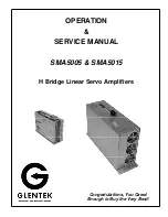
OPERATION 

SERVICE MANUAL 


SMA5005 & SMA5015 


H Bridge Linear Servo Amplifiers


Congratulations, You Cared 

Enough to Buy the Very Best! 

Содержание SMA5005

Страница 1: ...OPERATION SERVICE MANUAL SMA5005 SMA5015 H Bridge Linear Servo Amplifiers Congratulations You Cared Enough to Buy the Very Best ...

Страница 2: ......

Страница 3: ...ration of the Current Mode Amplifier SMA5015 Series Page 14 G Calibration Setup Record SMA5015 Series Page 15 APPENDIX Drawing SMA5015 Installation Page 18 Drawing SMA5015 Electrical Functional Block Schematic Page 19 Drawing SMA5015 Schematic Installation Power Supply Page 20 Drawing SMA5015 Printed Circuit Board Assembly Amplifier Page 21 Drawing SMA5015 Printed Circuit Board Assembly Power Supp...

Страница 4: ...mode for torque mode operation 3 Voltage mode SMA5015 only special order A basic velocity mode servo loop for a brush type motor is shown in figure A An external controller commands a given velocity RPM The velocity loop summing amplifier compares this command with the actual motor velocity supplied by a DC tachometer on the motor shaft and produces an error voltage proportional to the difference ...

Страница 5: ...available 24 75 VDC for stan dard SMA5005 module Basic versions Velocity and current modes SMA5015 is field configurable Fault protection Short from output to output short from output to ground amplifier RMS over current amplifier under over voltage SMA5015 only and amplifier over temperature Status indicator 7 segment LED display indicates amplifier status on the SMA5015 and LEDs indicate status ...

Страница 6: ...tions That is there are two basic baseplate assemblies namely 2 axis and 4 axis baseplate assemblies that have built in AC to DC power supplies un regulated and cooling fans The 2 axis baseplate assembly contains one AC to DC power supply one fan and up to two SMA5005 amplifier modules The 4 axis baseplate assembly contains one AC to DC power supply two fan and up to four SMA5005 am plifier module...

Страница 7: ...re Pm Total power watts dissipated in motor Vm Motor voltage 3 Pa Im x Vb Im x Vm Where Pa Total watts dissipated at amplifier From the above relationship it can be surmised that the worst case dissipation occurs when the amplifier has to deliver a high continuous current at a low motor speed i e less motor BEMF and more current For some applications a power resistor can be added in series with th...

Страница 8: ...ll down active high only SMA5015 pull up pull down active high active low Inhibit Same as Reset Limits Same as Reset Output Connections Motor MTR MTR Fault out SMA5005 Optically isolated can sink up to 50 mA active high only SMA5015 Open collector Pulled Up 5V active high or active low Bandwidth 10 kHz maximum and varies with motor inductance Status Indicator SMA5005 Green Run LED Red Inhibit LED ...

Страница 9: ... Single ended input 0 Single ended 1 Differential Velocity or Current Mode 0 Velocity 1 Current Input Logic Pull Up Voltage Select 15V 5V 0 15V 1 5V SMA5015 only Amplifier Configuration Code See configuration algorithm below Amplifier Model Number Stand Alone SMA5015 bbb 1A 1 Multi Axis 1 to 4 Axes Amplifier Model Number SMA5005 x bbb eA g 2 or 4 Axis Chassis Velocity Loop Compensation S Small Mot...

Страница 10: ... supplies Consult a Glentek applications engineer or sales person for assistance A Initial Start Up When applying power to start up your amplifier system for the first time we recommend you follow this procedure If you have already gone through this procedure you can skip to the appropriate calibration procedure 1 Check for any loose or damaged components 2 Check that all connections are tight 3 B...

Страница 11: ...lying a step input voltage adjust Current Limit RV5 for desired peak current The purpose of the following procedure is to set the system bandwidth to obtain a critically damped response or a one hook overshoot response with the maximum possible Tach Gain There are many possible settings of Tach Gain and Compensation which will yield the desired waveform The optimum setting will occur when Tach Gai...

Страница 12: ...pensation for the rest of the calibration procedure 11 With battery box still connected at J1 1 and J1 4 for single ended input or if your system uses the Differential input move battery box to J1 1 and J1 2 and remove micro shunt at J3 con nector set battery box for a known DC voltage Adjust the Signal Gain pot RV1 to obtain the desired motor velocity 12 If the motor is rotating in the wrong dire...

Страница 13: ...energize the motor 2 Slowly turn the Loop Gain RV6 pot CW fully The Motor should be stopped or turning slowly Set the Balance RV2 for 0V at J1 7 MTR I 3 Install a micro shunt at J3 connector across J3 1 to J3 2 Note For single ended signal input amplifier a micro shunt is permanently installed at J3 connector On the other hand the micro shunt should be removed for differential input ampli fier aft...

Страница 14: ...tors to discharge before taking measurements Note The balance pot should not be measured in this fashion set per step 3 in the calibration procedure Pot Dip Switches AMP1 AMP2 AMP3 AMP4 Signal Gain pot wiper TP2 to common ohms Tach Gain pot wiper TP3 to common ohms Compensation pot wiper TP4 to common ohms Current Limit pot wiper TP5 to common ohms Note Tach voltage is measured at J1 3 Common for ...

Страница 15: ...em bandwidth to obtain a critically damped response or a one hook overshoot response with the maximum possible Tach Gain There are many possible settings of Tach Gain and Compensation which will yield the desired waveform The optimum setting will occur when Tach Gain is as CW as possible and Compensation is as CCW as possible However the servo loop may become unstable the motor oscillates or hunts...

Страница 16: ...n pot CCW a few turns and repeat step 7 9 Do not adjust the Tach Gain or Compensation for the rest of the calibration procedure 10 With battery box still connected at J1 3 and J1 4 for single ended input or if your system uses the Differential input move battery box to J1 1 and J1 2 set battery box for a known DC voltage Adjust the Aux Gain pot RV2 or RV1 for differential input to obtain the desir...

Страница 17: ...nd adjust the AUX signal gain RV2 pot or RV1 for differential input to obtain the desired current gain of the amplifier 5 If the motor is rotating in the wrong direction for a given input polarity remove the power and reverse the motor leads 6 Remove the battery box and repeat step 2 7 Calibration complete Reconnect signal wires 14 F Calibration of the Current Mode Amplifier SMA5015 Series The amp...

Страница 18: ...efore taking measurements Note The balance pot should not be measured in this fashion set per step 3 in the calibration procedure Pot Dip Switches Amplifier Differential Gain pot wiper TP1 to common ohms Signal Gain pot wiper TP2 to common ohms Tach Gain pot wiper TP4 to common ohms Compensation pot wiper TP5 to common ohms Current Limit pot wiper TP6 to common ohms Note Tach voltage is measured a...

Страница 19: ...Glentek Inc 208 Standard Street El Segundo California 90245 U S A 310 322 3026 SMA5005 SMA5015 MANUAL 16 APPENDIX ...

Страница 20: ...Glentek Inc 208 Standard Street El Segundo California 90245 U S A 310 322 3026 SMA5005 SMA5015 MANUAL 17 THIS PAGE IS INTENTIONALLY LEFT BLANK ...

Страница 21: ...Glentek Inc 208 Standard Street El Segundo California 90245 U S A 310 322 3026 SMA5005 SMA5015 MANUAL 18 ...

Страница 22: ...Glentek Inc 208 Standard Street El Segundo California 90245 U S A 310 322 3026 SMA5005 SMA5015 MANUAL 19 ...

Страница 23: ...Glentek Inc 208 Standard Street El Segundo California 90245 U S A 310 322 3026 SMA5005 SMA5015 MANUAL 20 ...

Страница 24: ...Glentek Inc 208 Standard Street El Segundo California 90245 U S A 310 322 3026 SMA5005 SMA5015 MANUAL SMA5015 AMPLIFIER CIRCUIT BOARD ASSEMBLY 21 ...

Страница 25: ...Glentek Inc 208 Standard Street El Segundo California 90245 U S A 310 322 3026 SMA5005 SMA5015 MANUAL 22 SMA5015 POWER SUPPLY CIRCUIT BOARD ASSEMBLY ...

Страница 26: ...Glentek Inc 208 Standard Street El Segundo California 90245 U S A 310 322 3026 SMA5005 SMA5015 MANUAL 23 ...

Страница 27: ...Glentek Inc 208 Standard Street El Segundo California 90245 U S A 310 322 3026 SMA5005 SMA5015 MANUAL 24 ...

Страница 28: ...Glentek Inc 208 Standard Street El Segundo California 90245 U S A 310 322 3026 SMA5005 SMA5015 MANUAL SMA5005 CIRCUIT BOARD ASSEMBLY 25 ...

Страница 29: ...Glentek Inc 208 Standard Street El Segundo California 90245 U S A 310 322 3026 SMA5005 SMA5015 MANUAL 26 ...

Страница 30: ...Glentek Inc 208 Standard Street El Segundo California 90245 U S A 310 322 3026 SMA5005 SMA5015 MANUAL 27 ...

Страница 31: ...Glentek Inc 208 Standard Street El Segundo California 90245 U S A 310 322 3026 SMA5005 SMA5015 MANUAL 28 ...

Страница 32: ...Glentek Inc 208 Standard Street El Segundo California 90245 U S A 310 322 3026 SMA5005 SMA5015 MANUAL 29 ...

Страница 33: ......

Страница 34: ...Brushless servo amplifiers to 3 5KW PWM Pulse Width Modulated Brushless servo amplifiers to 51KW Permanent Magnet DC Brush Type Servo Motors Continuous Torques to 335 in lb Peak Torques to 2100 in lb Permanent Magnet DC Brushless Servo Motors Continuous Torques to 1100 in lb Peak Torques to 2200 in lb 208 Standard Street El Segundo California 90245 USA Telephone 310 322 3026 Fax 310 322 7709 www g...

Отзывы: