www.gdts.one
DOK4x HOIAO CxDEN · FD 9912
19
Air-to-water heat pump 16 kW with domestic hot water
English
6.7 Refrigerant pipe connections
!!
ATTENTION!
Work on the system must only be performed by authorised
and qualified after-sales service technicians.
Certain requirements with regard to pipe length and rise must
be complied with when installing refrigerant pipes. Once all
conditions are met, the connection of the connecting pipe from
the outdoor unit to the indoor unit can begin.
6.7.1 Requirements for the pipe length
and rise
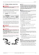
The indoor unit of the heat pump is already filled with refriger-
ant. The standard pipe length is 3.0 m. Up to a length of 7 m, no
additional refrigerant filling is required. For pipe lengths over
7 m, the system must be filled with additional refrigerant in ac-
cordance with the table.
!!
ATTENTION!
Incorrect filling with refrigerant could lead to faults during op-
eration.
!!
ATTENTION!
The length of the refrigerant line is calculated based on the
total line length from the respective connection point of the
indoor unit to the outdoor unit.
Incorrect refrigerant filling or refrigerant lines over 10 m result
in a risk of faults during operation and a complete failure of
the heat pump.
*Example: When installing the 9 kW model at a distance of
10 m, 420 g refrigerant must be added according to the follow-
ing calculation: (10 - 7) x 140 g = 420 g
HINWEIS
ºº
º
ºº
º
NOTE
If the indoor unit is mounted 2.5 m or more metres higher or
lower than the outdoor unit, a cooling technology specialist
must perform a separate check to ensure that the devices for
conveying the oil up and down the pipes have been installed
correctly in the exhaust gas pipe. The maximum rise (B) be-
tween the indoor and outdoor units is 5 m.
HINWEIS
ºº
º
ºº
º
NOTE
The specified operating data of the device refers to the stand-
ard pipe length, see device information.
6.7.2 Pipe connection
The connection points for the refrigerant lines must be estab-
lished using the brazing process. All generally applicable instal-
lation and work steps must be followed for this.
During the brazing process, the pipe system must be flushed
with an inert gas (e.g. nitrogen). The adjacent components must
be suitably cooled to prevent them being damaged.
6.7.3 Leak test and evacuation
Air and moisture in the cooling system have unwanted effects
as outlined below.
1) The pressure in the system increases.
2) The operating current increases.
3) The cooling (or heating) output falls.
4) Moisture in the cooling circuit can freeze and block the
capillary tubes.
5) Water can cause corrosion on parts in the cooling
system.
This means that the connection pipes must be checked for
leaks and pumped empty to remove any moisture and non-
condensable gases from the system.
Step 1: Preparation
Ensure that every pipe (liquid and intake side) between the in-
door and outdoor unit is connected correctly. Ensure that both
maintenance valves on the liquid and intake of the indoor unit
are closed at this point.
Step 2: Leakage tightness test
Connect a dry nitrogen gas cylinder (with Schrader) on the
maintenance valve.
Apply 40 bar dry nitrogen to the system. Close the cylinder
valve once the test pressure is reached. The next step is to
search for leaks with liquid soap.
HINWEIS
ºº
º
ºº
º
NOTE
In order to prevent liquid nitrogen from entering the cooling
system, the top side of the gas cylinder must be higher than
the bottom side when pressure is building in the system.
All pipe connections (internal and external) must be
checked for leaks with liquid soap. Bubbles indicate a leak.
The soap must then be wiped away with a clean cloth.
If no leaks are found on the system, drain off the nitrogen.
Model
Pipe size (mm)
(external diame-
ter x wall thick-
ness)
Length A (m)
*additional
refrigerant
(g/m)
Gas
Liquid
Normal
Min.
Max.
16 kW
18 x 1
12 x 1
7
3
10
140
Outdoor unit
Indoor unit
A
B
Outdoor unit
Indoor unit
A
B
max. 5 m
max. 5 m
Содержание 16CHOIAOC6
Страница 2: ......

