Page 20
Page 21
INSTALLATION
INSTALLATION
PRIMARY HEAT SOURCE CONTROL
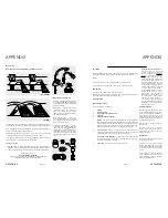
WIRING DIAGRAM
Normally Closed
2 Port Valve
Normally Open 2 Port Valve
E
E
L
N
N
SL
PL
ML
5 A
Lo
ca
l
double
po
le
is
ol
at
or
CH
Pr
og
ra
m
m
er
L
N
1
4
3
R
oo
m
T
he
rm
os
ta
t
O
N
OFF
O
N
O
FF
1
E
2
4
3
Control Stat 2
1
C
2
Pipe Thermostat 1
1
C
2
1
2
3
4
5
6
7
8
9
10
11
12
To
rre
nt
Stainless electric only (direct option) and auxiliary heating control system
Junction
N
L
E
1
2
3
on
of
f
on
of
f
Overheat
Stat
1
C
on
O
N
O
FF
24 hou
r do
m
es
tic
s
uppl
y
[O
ff-
peak du
rin
g
00:00 – 07:
00
E7]
O
N
O
FF
M
C
B
O
N
OFF
M
C
B
B16
O
N
O
FF
M
C
B
O
N
O
FF
M
C
B
O
N
OFF
M
C
B
Ho
t
W
ater
To
p
O
n-Peak 3
kW
Im
m
er
sion heater
Bott
om
O
ff-
Peak
3
kW
Im
m
er
sion heater
O
ff-p
eak
controller
2 Pole Isolator sw
itc
h
Consumer unit
Central heating pum
p
E
N
L
Clock
2
Primary Heat Source Control Sensor / Thermostat Pockets
In all thermal stores heated by a primary heat source e.g. a boiler (with the exception of
direct thermal stores heated by immersion heaters with integral control and overheat
thermostats), the thermostat and sensor pockets for controlling the system are be
designed and located to sense the bulk water temperature.
The Torrent Stainless thermal stores have been fitted with four store thermostat/sensor
pockets, with their position complying with the HWA Performance Specification for
Thermal Stores 2010 (section 6.4).
When two control thermostats / sensors (S1 and S2) are fitted their operating control
logic should be as follows: -
(a) The primary heat source should be switched ‘ON’ when both sensors (thermostats),
S1 and S2 are calling for heat.
(b) The primary heat source should only be switched ‘OFF’ when both sensors
(thermostats), S1 and S2 stop calling for heat.
Note: A typical wiring arrangement for 2 thermostats is shown in figure 8.1.
Store Thermostat(s) For Controlling Primary Heat Source
The specified store thermostat setting for controlling the primary heat source
should prevent unnecessary cycling of the heat source (e.g. the boiler) on its internal
thermostat for efficient operation.
All types of thermal stores must be supplied with one or more thermostats or electronic
controls with an adjustable range of up to 90°C and span not greater than 70°C. The
switching differential of the thermostat should be 6°C±1°C.
A strap on surface cylinder thermostat is not considered suitable for this application.
V
S1
V
S2
S2
S1
HWA Specification for thermal stores
2010
Final version: 21/03/2010
51/78
8.
SPECIFICATION OF COMPONENTS
8.1
GENERAL
All types of thermal stores can either be supplied with all the components ready fitted
and wired or full wiring and system configuration details, and the list of recommended
components (e.g. pumps, delay timers) should be provided in the design and installation
manuals.
8.2
STORE THERMOSTAT(S) FOR CONTROLLING PRIMARY HEAT SOURCE
8.2.1
The specified store thermostat setting for controlling the primary heat source
should prevent unnecessary cycling of the heat source (e.g. the boiler) on its
internal thermostat for efficient operation.
8.2.2
All types of thermal stores must be supplied with one or more thermostats or
electronic controls with an adjustable range of up to 90
o
C and span not greater
than 70
o
C. The switching differential of the thermostat should be 6
+
1
o
C.
8.2.3
A strap on surface cylinder thermostat is not considered suitable for this
application.
8.2.4
The store control thermostats should be either:-
(a)
Non-user adjustable and pre-set to switch off at the specified temperature to
guarantee the performance.
OR
(b)
Capable of being locked in the correct user zone and should switch off at the
specified temperatures within the zone to guarantee the performance.
8.2.5
For improved utilisation of thermal store and lower in-use system losses, it is
recommended that the thermal stores of capacity greater than 250 litres can be
c
1
2
c
1
2
c
c
230Vac, 50HZ
Mans supply
L N
Bottom
store
thermostat
Top store
Thermostat
2 Pole CO relay
230Vav coil
NC
NO
NC
NO
L
N
Heat source
Control supply
C = Common contact
C = Common
C-1 = Close on temperature rise
NO = normally open
C-2 = Close on temperature drop
NC = normally closed
Figure 8.1 : Example of twin thermostat control circuit wiring for thermal stores
Содержание Torrent Stainless OV
Страница 22: ...Page 42 Page 43 NOTES NOTES ...


