gledhill mCHP BMA 225 Скачать руководство пользователя страница 26

Page 26

5.0 INSTALLATION AND WIRING

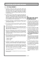
5.1   SITE REQUIREMENTS

(a)  The appliance is designed to be installed in an airing/cylinder cupboard on the 

100mm  high  plinth  supplied  with  the  appliance  and  the  minimum  relevant 
dimensions are provided in section 3.  The minimum dimensions shown in figure 
3.2  and Table  3.1,  allow  for  the  passage/connection  of  pipes  to  the  appliance 
from any direction as long as the appliance is installed on the base provided. if 
the installation base is not used, extra space may be needed to allow connection 
to the appliance pipework.

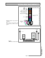
(b)  A suitable location will normally be needed for the separate feed and expansion 

cistern. This will often be at a high level in the cupboard housing the BoilerMate. 
The appliance CF & OV pipework assembly has been designed so that the cistern 
can be fitted on top of the BoilerMate appliance if required.   The dimensions and 
clearances are provided in section 3. The location will need to provide a suitable 
route for the cold feed and expansion pipe as well as the open safety vent pipe 
and also a suitable route for the warning overflow pipe. 

(c)  Because of ease of installation it is recommended that the cupboard construction 

is finished and painted before installation of the appliance. The cupboard door 
can be fitted after the installation. 

(d)  if the unit needs to be stored prior to the installation, it should be stored upright 

in a dry environment and on a level base floor. For handling instructions please 
see page 4 of this manual.

(e)  The floor of the cupboard must be level and even and capable of supporting the 

weight of the appliance when full. Also installation and maintenance access is 
needed to the front of the appliance and above the F & E cistern. See Technical 
Specifications (section 3) for further details.

(f)  The appliance is designed to operate as quietly as practicable. However some noise 

from pumps etc. is inevitable in any heating system. This will be most noticeable 
in cupboards formed on the bulkhead or at the mid span of suspended floor. in 
these cases the situation can be improved by placing the appliance on a suitable 
sound deadening material.

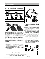
(g)  When using push fit connectors with the flexible hose kits it is important to check 

that they are compatible. We currently recommend push fit connectors from the 
following manufacturers. The installer must check and confirm the suitability of 
any other types of push fit connectors.


•    Hepworth –Hep

2

O BiTite


•    John Guest – Speedfit


•    Yorkshire – Tectite

(h)  The  cupboard  will  normally  be  at  marginally  higher  temperature  than  in  a 

conventional system and the design of the door and the cupboard will need to take 
this into account. However no ventilation is normally required to the cupboard.

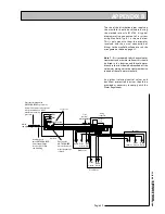
(i)  A  230V/50Hz  electrical  supply  must  be  available  which  is  correctly  earthed, 

polarized  and  in  accordance  with  the  latest  edition  of  the  iEE  regulations  for 
electrical installations BS 7671. The connection must be made using a double-pole 
linked isolator with contact separation of 3mm in both poles which is located 
within 1m of the appliance and it must only serve the appliance.


The rating of the electricity supply to the mCHP_BoilerMate must be 6.5kW at 
230V ac (See also 3, section 4).

(j)  The location site chosen for installing the mCHP unit must meet the requirements 

of its manufacturer.
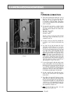
5.2
PREPARING APPLIANCE 
FOR INSTALLATION

(a)  Details of the recommended positions for 

the  termination  of  first  fix  pipework  are 
provided in section 3, figure 3.2a and 3.2b. 
The pipework can be located or its position 
checked using the template provided with 
each appliance. if these have been followed, 
then the installation is very simple and much 
quicker than any other system.

(b)  The appliance is supplied shrink wrapped 

on  a  timber  installation  base.  Carrying 
handles  are  also  provided  in  the  back 
of  the  casing. The  appliance  should  be 
handled carefully to avoid damage and the 
recommended method is shown on page 
2. 

The manual handling operations will 

need to comply with the requirements of 
Manual handling Operations Regulations 
issued by H.S.E.


Before  installation  the  site  requirements 
should be checked and confirmed acceptable. 
The plastic cover and protective wrapping 
should  be  removed  and  the  installation 
base provided with the appliance placed in 
position.

(c)  The  appliance  can  then  be  lifted  into 

position  in  the  cupboard  on  top  of  the 
base. The front panel can then be removed 
by unscrewing the 2 screws and lifting the 
door  up  and  out,  ready  for  connection  of 
pipework and electrical supplies.

(d)  The  feed  and  expansion  cistern  support 

shall be installed ensuring that the base is 
fully supported and the working head of the 
appliance is not exceeded (10m maximum). 
Also  the  recommended  access  should  be 
provided  for  maintenance  as  shown  in 
section 3.  

Содержание mCHP BMA 225

Страница 1: ... STORE FOR USE WITH mCHP UNITS IN DOMESTIC DWELLINGS ALL MODELS COMPLY WITH THE WATER HEATER MANUFACTURERS SPECIFICATION FOR INTEGRATED THERMAL STORES TM benchmark Thecodeofpracticefortheinstallation commissioning servicingofcentralheatingsystems mCHP BoilerMate A C L A S S Model Numbers mCHP BMA 225 mCHP BMA 235 iSSUE 4 06 08 ...

Страница 2: ...themCHPapplianceinstallation instructions before installing or commissioning the appliance Leave these instructions and the Benchmark Log Book in the pocket provided on the back of the appliance front panel Building Regulations and Benchmark Commissioning The Building Regulations England Wales require that the installation of a heating appliance be notified to the relevant Local Authority Building...

Страница 3: ...4 1 HOT AND COLD WATER SYSTEM 22 4 1 2 Use in Hard Water Areas 23 4 1 3 Hot and Cold Water Distribution Network 23 4 1 4 Taps and Shower fittings 23 4 1 5 Dead Leg Volumes 23 4 2 SPACE HEATING SYSTEM DESIGN 24 4 3 mCHP CIRCUIT DESIGN 25 5 INSTALLATION AND WIRING 26 5 1 SITE REQUIREMENTS 26 5 2 PREPARING APPLIANCE FOR INSTALLATION 26 5 3 PIPEWORK CONNECTIONS 28 5 4 ELECTRICAL WIRING 29 5 4 1 Genera...

Страница 4: ...nt and on a level base floor Note Although the above guidance is provided any manual handling lifting operations will need to comply with the requirements of the Manual Handling Operations Regulations issued by the H S E The appliance can be moved using a sack truck on the left hand face although care should be taken and the route should be even In apartment buildings containing a number of storey...

Страница 5: ...t must however remain that of our customers mCHP appliance manufacturers and any expert or consultants concerned with the installation s Therefore please note that a We do not therefore accept any responsibility for matters of design selection or specification for the effectiveness of an installation containing one of our products b All goods are sold subject to our Conditions of Sale which are se...

Страница 6: ...alves or expansion vessels This is achieved by passing the mainswaterthroughaplateheatexchanger The outlet temperature of the domestic hot waterismaintainedbythesystemcontroller at about 52o C at 18 l min by regulating the speed of the pump circulating the primary water from the store through the plate heat exchanger Itevensoutthefluctuatingandintermittent demands for space heating and hot water a...

Страница 7: ...dabovethe optionalpolyphosphate type inhibitor should be specified at the time of order However this will need to be fitted by the installer at a suitable point in the cold water supply to the appliance If scale should ever become a problem the plate heat exchanger is easily isolated and quickly replaced with a service exchange unit which can be obtained at a nominal cost from Gledhill Because thi...

Страница 8: ... heating circuit is a separate sealed system and will require the installer to buy and fit a standard heating circuit expansion kit see figure 2 2 for the connection arrangements The space heating demand is controlled by the heating programmer and the room thermostat and its operation is independent of the operation of the mCHP Whenboththespaceheatingprogrammerand the room thermostat are calling f...

Страница 9: ... and space heating demands are active and the average store temperature is less than T_CH_boost1_On set point and the rate of temperature rise in the store is less than the R_CH_boost1 set point the controller will send the signal to the mCHP to run in boost mode If the store temperature falls below the pre set limit see table 3 5 the controller will either switch off the space heating pump or run...

Страница 10: ...selected and this will be indicated by constantly lit red led on the front panel After the switch backup system has been selected it will operate the same as the mCHP using the same set points as discussed in previous sections and also with same sensor error handling routines If the store temperature exceeds 95ºc the controller will shut the heat source and activate the overheat safety trip lockou...

Страница 11: ...H OPERATION By moving the mode rocker on the front panel from normal to switch position the electric backup boiler switch can be used as an alternative heat source for hot water and central heating should there be a failure of the mCHP boiler See 2 2 7 Electric Backup Facility for further details 2 3 5 CH Clock The BoilerMate when used with an mCHP appliance is designed to be heated 24h day and co...

Страница 12: ...ns 100mm high plinth B C 600mm Min clearance for servicing F E Cistern A 300mm Figure 3 1 Clearances and cupboard dimensions 210 150 70 50 475 510 560 550 220 170 220 185 65 65 22 22 22 22 22 22 22 15 mCHP R HF HR mCHP Flow CF DHW OV CF Figure 3 2 Pipe Connections 530 All dimensions in mm BMA 225 BMA 235 A 2050 2190 B 630 800 C 610 610 3 0 TECHNICAL SPECIFICATION Note For appliance dimensions see ...

Страница 13: ...elving etc in the case of airing cupboard etc must be added Table 3 1 Technical Specification of mCHP BoilerMateA CLASS Physical Data BMA225 BMA235 Storage volume Nominal Storage Capacity litres 186 210 Appliance weight Empty kg 49 53 Full kg 235 263 Appliance dimension height mm 1300 1440 width mm 530 530 depth mm 595 595 Maximum working head Thermal Store mWG 10m Suitable only for open vented sy...

Страница 14: ...6 W 6 500 approximate 28A Supply must rated at 32A minimum Maximum power consumption at 230V ac 50Hz Standby mode W 30 mCHP Operating 7 W 300 Switch Operating W 6 300 Control Boiler system W 1 x 6A MCB Control Boiler system W 1 x 6A MCB Internal circuit Switch backup 2 x 16A MCB Protection devices Notes 1 All mCHP BoilerMateA CLASS models are fitted with a 6kW electric backup system i e Switch whi...

Страница 15: ...ex overheat sensor S 9 2 x Store single sensor S 10 1 x Cold water inlet single sensor S 11 1 x Hot water outlet single sensor S 12 Front panel display S 13 2 x 16A MCB for Switch backup circuit S 14 1 x 6A MCB for appliance control circuit S 15 DIN Rail wiring terminals control gear S 16 PJN 147 Appliance controller S 17 Electromechanical Programmer S 18 Automatic bypass valve 19 Feed and expansi...

Страница 16: ...ASS willoperate at mains inlet pressure as low as 1 bar and as high as 5 bar the preferred range is 2 3 bar dynamic Typicalhotwaterperformanceoftheapplianceis showninfigure3 5 Theperformancecomparison is shown for continuous hot water draw off at 18 l min when the store is charged to nominal 77o C andthecoldwaterinlettemperatureis10o C Also during the draw off it is assumed that there is no heat i...

Страница 17: ... L 2 3 4 1 ON SPD1 2A OPTIONAL EXTRA IF FITTED PART No XB142 SCALE INHIBITOR 2 x 3kW Heating Elements S 3 S 4 S 5 S 6 Store overheat Top Cold Water IN Domestic Hot Water OUT Store Bottom 10K Resistor Store Middle S1 S2 ID_RESISTOR SENSOR LEGEND BLUE Bl BROWN Br GREEN YELLOW G Y WIRE COLOUR LEGEND BLACK ORANGE YELLOW WHITE RED B Or Y Wh R mCHP BOILERMATE A Class N with Clock Factory Standard FACTOR...

Страница 18: ...ont panel See figure 6 2 for further details of the 2 digit digital display 3 6 APPLIANCE TYPE SELECTION The mCP BoilerMateA CLASS is fitted with an identity ID resistor which is read by the controller for comparison with the appliance type code set on the controller The two must match for the controller appliance to function Thereforeifeithertheappliancecodesettingor the ID resistor is wrong the ...

Страница 19: ...display shown in figure 6 2 indicates the status of the appliance inputs and outputs by switching on the appropriate segments of the display 3 6 2 SENSOR TEMPERATURE The sensors used in this appliance are listed in table 3 7 In this mode the current temperature read by the selected sensor is displayed The temperature reading is displayed by alternatively flashing the sensor number and its temperat...

Страница 20: ...point Sensor S6 54ºC Hot water priority OFF set point Sensor S6 58ºC 3 1 CH Pump max speed 255 CH Pump min speed 110 CH return temperature set point Sensor S5 55ºC 4 Bottom store sensor S5 ON set point 60ºC Bottom store sensor S5 OFF set point 70ºC 5 Middle store sensor S6 ON set point 68ºC Middle store sensor S6 OFF set point 77ºC 6 mCHP boost ON set point in HW only mode T_HW_boost_on 52ºC mCHP ...

Страница 21: ...1 T_TANK_BOTTOM_OPEN 11 OVERHEAT DIFFERENCE ERROR 36 GP_LOST_ERROR 2 T_TANK_MIDDLE_SHORTED 12 T_MAX LOCK ERROR 37 T_OVERHEAT_ _OPEN 3 T_TANK_BOTTOM_SHORTED 38 OPEN_SENSOR_1 4 EB_FAILURE 39 OPEN_SENSOR_2 40 T_ID_OPEN 41 OPEN_SENSOR_4 17 15MS ERROR 42 OPEN_SENSOR_5 18 FLAG BYTE INTEGRITY ERROR 43 OPEN_SENSOR_6 19 AD_HI_CPL ERROR 44 T_OVERHEAT_2_OPEN 20 AD_LO_CPL ERROR 45 SHORTED_SENSOR 21 REGISTER E...

Страница 22: ... 1 Typical hot and cold water distribution pipework in a dwelling 4 1 1 MAINS PRESSURE AND WATER SUPPLY a mCHP_BoilerMate is designed to be connected directly to the mains and fulfil the requirements of Water Byelaw 91 and therefore do not require a check valve to be fitted to the supply pipe However should ancillary equipment requiring a non return valve is to be fitted to the same mains supply a...

Страница 23: ...fitting appropriate flow regulators to each hot and cold water outlets These must be fitted in cases where the final branch pipe sizes are not as recommended in c below or the water pressures are above the recommended 2 3 bar range c Alternatively the tee offs to the outlets should be in 10mm except for bath and shower which should be in 15mm I metre minimum length d The hot water supply to a show...

Страница 24: ...ts is shown in figures 3 3 and 3 4 The appliance connection details are shown in figure 3 2 and table 3 1 in the technical specification section 3 If the appliance is at the highest point of the system a manual air vent is provided on the appliance However if any point of the heating system is higher than the appliance then an air vent must be fitted at the highest point in the system At least one...

Страница 25: ...n the appliance must not exceed 1 0 bar The water level in the F E cistern should be at least 250mm above the highest point of the circuit from the mCHP unit h Overflow pipe The overflow warning pipe should be in 20mm internal diameter pipe of suitable material for use in heating systems in accordance with BS 5449 such as copper It should have continuous fall and discharge in a conspicuous externa...

Страница 26: ...it connectors from the following manufacturers The installer must check and confirm the suitability of any other types of push fit connectors Hepworth Hep2 O BiTite John Guest Speedfit Yorkshire Tectite h The cupboard will normally be at marginally higher temperature than in a conventionalsystemandthedesignofthedoorandthecupboardwillneedtotake this into account However no ventilation is normally r...

Страница 27: ...pply Neutral N 230V Permanent Live L 230V From mCHP 230V ac 2 mCHP_boost switched live L 3 Electric boost on signal L 1 mCHP_on off switched live L Room stat switched live L Programmer HW switched live L Programmer CH switched live L N L E Mains supply 230V 50Hz 32A 6mm2 4 230V 50Hz Supply 2 Pole 32A Isolator 2 Pole 6A Isolator 230V 50Hz mCHP Appliance mCHP BoilerMate Room thermostat 230V 50Hz 32A...

Страница 28: ...y open vent should be installed between the appliance and the feed and the expansion cistern NOTE 2 F E cisterns are provided with the 235 model The ballvalve should not be fitted in the same cistern as the cold feed connection and the positionoftheseandtheinterconnectingpipework should be arranged to reduce the possibility of stagnant pockets of water in the cisterns f Itisnormallyenvisagedthatth...

Страница 29: ...upplies to both the BoilerMate and the mCHP unit are switched off before commencing electrical work The mCHP BoilerMate is supplied with a pre wired 2m long twin E cable rated at 32A Connect this cable to the local BoilerMate isolator See figure 5 4 b When the thermal store requires heating the BoilerMate controller will generate a 230V ac on off signal at terminals labelled SL O and N These termi...

Страница 30: ...tols and mCHP wiring diagram for models fitted with programmer Colour Legend Br Brown Bl Blue B Black Gry Grey G Y Green Yellow Gry Gry Gry Gry B B B B B Bl Bl Bl Bl Bl Bl Bl G Y G Y G Y Wh G Y G Y G Y G Y Br Br Br Br Br Br Br Br Br Br Please refer to the Installation Service manual supplied with the WhisperGen appliance before making connections ON OFF Note Supply to be brought directly from cons...

Страница 31: ... 50Hz 32A 6mm 10mm 6 0mm Flat twin earth Boilermate cable Local 2 pole isolator within 2m of Boilermate G Y WhisperGen mCHP 230V 50Hz supply fused at 8A Anti surge HRC fuse Bl Bl G Y G Y Br Br Please refer to the Installation Service manual supplied with the WhisperGen appliance before making connections Local 2 pole isolator within 2m of appliance Please refer to programmer instruction manual for...

Страница 32: ...ion of scale and corrosion inhibitor such as the Fernox Superfloc cleaning agent and Fernox MB1 protector The correct use of cleaning agent and of the correct strength of inhibitor is essential for the efficient and long life of the complete system Failure to do this correctly will result in premature corrosion of the boiler blocking of the waterways and neither of these situations will be covered...

Страница 33: ... panel display from normal to switch position The electric backup operation can now be observed 6 4 COMMISSIONING SPACE HEATING a The central heating is best commissioned when the store is hot and therefore should be carried out after procedure 6 3 b Setheatingclocktocontinuousandensure thattheroomthermostatiscallingforheat This will be indicated by display segments V1 3 and V1 4 being on respecti...

Страница 34: ...c Advise on mCHP operation and maintenance advised in mCHP manual d Explain how to select the emergency backup electric boiler switch operation if there is a failure of the mCHP e Handoverapplianceandroomthermostatuserinstructionsandputthecompleted Benchmark logbook and the appliance instruction manual in the pocket on the inside of the appliance front panel f DON T place any clothing or other com...

Страница 35: ...traight valve OUTLET 7308123 GT135 GT133 10 2 x 3kW switch immersion heater Backer 11 Main PCB controller Pijnenburg 147 3GS controller 147 3GS GT103 12 Bottom store sensor Tasseron Single sensor TSK10B4 GT198 13 Middle store sensor Tasseron Single sensor TSK10B4 GT198 14 Top OHT sensor Tasseron Duplex sensor TSK11B4 GT199 15 Front panel display RH Technical Membrane overlay 16 Front panel display...

Страница 36: ...NS FOR SHOWERS 4 FIXING OPTIONS FOR TAPS MIXERS 1 MK Range Combined Regulators Aerator for screwing onto Taps Mixers with internal or external threads on their noses Anti Vandal models also available 2 MR05 T Range Internal Regulators Push fit intoTap or Mixer seats Produced in three sizes 12 5mm BS1010 12mm 10mm Flangeless models also available for Taps with Low Lift washers 3 MXFStandardRange Sc...

Страница 37: ...ed 595mm 2 No 6mm fixing holes 18 l mm 12 l mm 9 l mm 9 l mm 9 l mm 9 l mm 12 l mm inlet 55mm 18 l mm 12 l mm 9 l mm 9 l mm 9 l mm 9 l mm 9 l mm 9 l mm 9 l mm 9 l mm 12 l mm inlet 165mm 595mm A hot B cold blank blank 18 l min 12 l min 12 l min 9 l min 9 l min 9 l min 9 l min 9 l min 12 l min 18 l min inlet 595mm C D 18 l min 12 l min 12 l min 9 l mm 9 l mm 9 l mm 9 l mm 9 l mm 9 l mm 9 l min 9 l m...

Страница 38: ...nd the resistance characteristics of the pipes The examples presented below are for 15mm copper pipe in table 1 and for plastic pipework in table 2 The preferred solution where space will allow An optional location where cupboard space is tight Table 1 Maximum equivalent pipe length in 15mm copper Inlet pressure bar Maximum equivalent length of pipe m 9 l m 12 l m 18 l m 2 0 25 10 5 2 5 75 30 15 3...

Страница 39: ...ink should be branched off the cold water main prior to the treatment device instead of the cold water manifold Any other isolating control valves and backflow protection devices should be provided as necessary to comply with the Water Regulations Bath Toilet cistern Hand basin Toilet cistern Hand basin Hand basin Toilet cistern Mains supply Shower DW Kitchen sink Kitchen En Suite Bathroom Check v...

Страница 40: ...ld be fixed to the system in a prominent location Where a combi boiler and or a hot water storage vessel is installed in areas where the mains water can exceed 200ppm Total Hardness as defined by BS 7593 1993 Table 2 a scale reduction device should be installed in accordance with the boiler manufacturer s instructions The levels of water hardness may be measured using a water hardness test kit BUI...

Страница 41: ...easy lifting at the top of the product Each appliance is supplied with a pallet which has been attached to the unit via the packaging The pallet will also allow for one or two persons to get a good hold e Taking the lead for team lifts As more than one person is required for these products ensure that one person is taking the lead This may be you so ensure that each person that is helping is made ...

Страница 42: ...ials or workmanship we will either repair or supply replacement at our option with the closest substitute in the case of any obsolete product to any address in Great Britain i free of all charge during the first year after delivery by us ii thereafter at a charge of one tenth of the then current list price and any copper price supplement and delivery charge during the second year after delivery by...

Страница 43: ...ubject to of any other contract between the Purchaser and us which at the time of payment of the full price of the goods sold under this contract have been delivered to the Purchaser but not paid for in full c until property in the goods supplied hereunder passes to the Purchaser in accordance with paragraph 2 above i the Purchaser shall hold the goods in a fiduciary capacity for us and shall stor...

Страница 44: ......

Отзывы: