


Page 8
2.0
TEcHNIcAL INFOrMATION
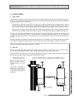
2.2 OPErATION
The main components of the boiler are shown in figures .a and .b. The
status of the boiler and the central heating and hot water demands and the
corresponding boiler functions are indicated on the 4 x 7 segment display as
described in section ..(e).
Flue Gas Sensor
Expansion Vessel
(7 Litre)
Heat Exchanger
Burner Assembly
Window
Spark Electrode
Flame Sensing Electrode
Overheat Thermostat
Boiler Flow Temperature
Control Thermostat Sensor
Fan Assembly
Gas Valve Assembly
Air/Gas Venturi
Figure 2.2a
Condensate Trap Cap
(for cleaning)
Condensate Drain
Connection
Air Vent
Diverter Valve
Modulating Pump
DHW Flow Rate &
Temperature Sensor
CH Bypass Flow
Adjusting Screw
Figure 2.2b
Boiler Pressure & Return
Temperature Sensor
Pressure Relief
Valve
Drain Valve
Содержание GB35C
Страница 49: ...Page 49 CONDENSING COMBI BOILER ...
Страница 50: ...Page 50 ...
Страница 53: ...Page 53 CONDENSING COMBI BOILER ...
Страница 56: ......


