Labelling
Function
Audio R in
Input, audio signal, right
Audio L in
Input, audio signal, left
Audio GND
GND audio inputs
Audio R out
Output, audio signal, right
Audio L out
Output, audio signal, left
Audio GND
GND audio outputs
Video in
Input, video signal
Video GND
GND video signal
Table: Connection assignment, audio and video connections
Use the Ethernet connection (32) together with the supplied Ethernet adapter plug and Ethernet
adapter cable to connect to the IP network.
Pay attention to the correct colour assignment of the wires, EIA/TIA-568-A or -B. This can be
found in the documentation of the installed network components and routers.
i
The Ethernet connection on the device is carried out according to EIA/TIA-568-B.
o
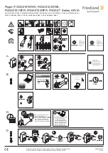
Connect Ethernet cable to the Ethernet adapter plug. To do this, strip the Ethernet wires,
do not skin, and insert into the cover of the adapter plug. Shorten any wires that are jutting
out and push the cover onto the adapter plug in the correct position (Figure 7).
o
Connect the supplied Ethernet adapter cable to the terminal (32) and Ethernet adapter
plug.
Figure 7: Connection of adapter connector to Ethernet cable
o
Install device in panel-mounted housing. Use the screws supplied.
o
Insert the Design frame in the correct direction into the designated brackets and push down
and to the left - down and to the right for vertical mounting - to fix it.
5.2 Commissioning
Control 9 KNX: Loading physical address
o
Press the programming button (9).
The programming LED (8) lights up.
o
Assign physical address.
The programming LED (8) goes out.
Control 9 KNX: Loading the application software
i
The project design and commissioning are performed using external project design and
commissioning software.
o
Establish connection to the commissioning PC via IP connection.
82576732
03.06.2016
8/11
KNX
Control 9 Client, Control 9 KNX


