HS-50 & HS-100
Doc. No 1199-PS-0035 Issue 3
June 2021
___________________________________________________________________________________________
Page 42
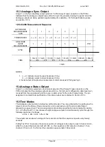
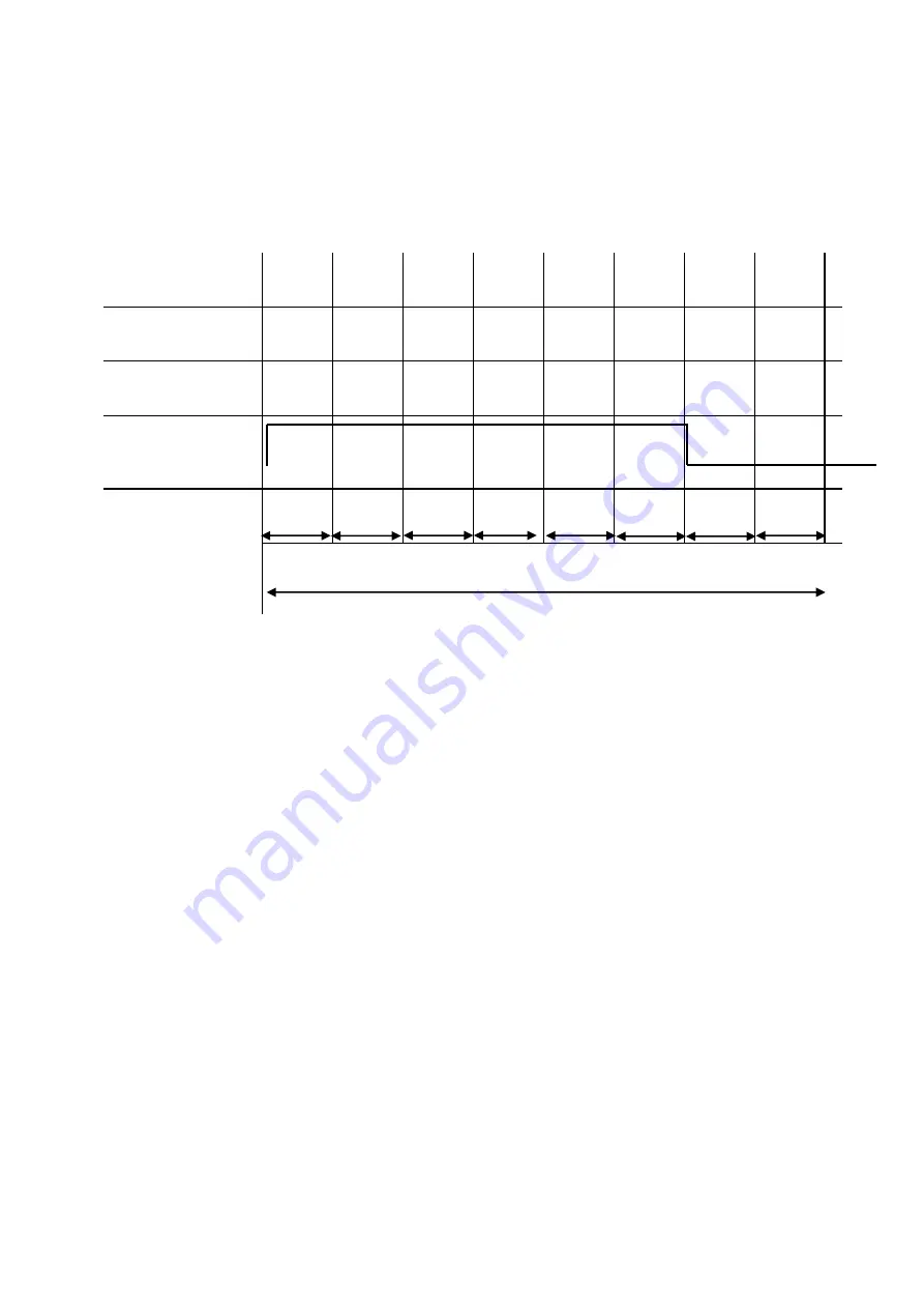
15.3 Analogue Sync. Output
A logic 1 on the Sync/Auxiliary output (pins 6 & 7 of the 9-way D type connector on the PCI/A)
indicates that the analogue outputs have settled. A logic 0 is generated during the period when the
analogue outputs are being updated (approximately 2ms duration). For full specifications please
see section 10.1.4.
1210-K-068 Measurement Sequence
ULTRASONIC
MEASUREMENT
AXIS
1
1
2
2
3
3
TRANSDUCER
L
U
U
L
L
U
U
L
L
U
U
L
ANALOGUE
INPUT
MEASUREMENT
1
2
3
4
5
6
PRT
SYNC.
TIME
1.14mS
1.14mS
1.14mS
1.14mS
1.14mS
1.14mS
0.88mS
0.88mS
10mS
NOTES:
1. L
U indicates lower to upper transducer firing
U
L indicates upper to lower transducer firing
2. Serial output of the previous measurement commences as SYNC goes high
15.4 Analogue Status Output
A logic 1 on the status output (pin 24 wrt signal ground of the 25-way D type connector on the
PCIA) indicates that the analogue outputs are valid (i.e. the full set of configuration data have been
received from the anemometer and there are no data errors for the current output data). The pin
assignment and electrical specification of the status output are contained in Section 10.1.4.
15.5 Test Modes
The analogue output system includes two self-test modes. They are activated by the pulling low the
relevant pin on the 25-way D type connector, and remain active until the pin is pulled high or
allowed to go open circuit. The pin assignment and electrical specification are contained in section
10.1.4. Pulling Test Pin 1 low causes all eight analogue outputs to simultaneously cycle through the
following sequence of voltages:
-2.50v, -1.25v, 0.00v, 1.25v, 2.50v
The outputs remain at each voltage for four seconds so that the sequence repeats every twenty
seconds.
Pulling Test Pin 2 low causes the same sequence of voltages to be output on each channel in turn,
while the unused channels are held at 0.00v, i.e. the sequence is first output on channel 1, then
channel 2, then 3 etc. For this test the complete sequence lasts 160 seconds.
Содержание 1199-PK-085
Страница 1: ......


