background image

MDE-4780D FlexPay™ EPP and SCR Kit (EPK ECIM RF) Installation Instructions for Encore® S E-CIM™ · December 2015

Page 5

Important Safety Information

Important Safety Information

Notes: 1) Save this Important Safety Information section 

in a readily accessible location.

 2) Although DEF is non-flammable, Diesel is 

flammable. Therefore, for DEF cabinets that are 
attached to Diesel dispensers, follow all the 
notes in this section that pertain to flammable 
fuels.

This section introduces the hazards and safety precautions 
associated with installing, inspecting, maintaining or servicing 
this product. Before performing any task on this product, read 
this safety information and the applicable sections in this 
manual, where additional hazards and safety precautions for 
your task will be found. Fire, explosion, electrical shock or 
pressure release could occur and cause death or serious injury, 
if these safe service procedures are not followed. 

Preliminary Precautions

You are working in a potentially dangerous environment of 
flammable fuels, vapors, and high voltage or pressures. Only 
trained or authorized individuals knowledgeable in the related 
procedures should install, inspect, maintain or service this 
equipment

.

Emergency Total Electrical Shut-Off

The first and most important information you must know is how 
to stop all fuel flow to the pump/dispenser and island. Locate 
the switch or circuit breakers that shut off all power to all fueling 
equipment, dispensing devices, and Submerged Turbine 
Pumps (STPs).

The EMERGENCY STOP, ALL STOP, and 
PUMP STOP buttons at the cashier

s station 

WILL NOT shut off electrical power to the 

pump/dispenser. This means that even if you 
activate these stops, fuel may continue to flow 
uncontrolled. 

You must use the TOTAL ELECTRICAL 

SHUT-OFF in the case of an emergency and not 
the console

s ALL STOP and PUMP STOP or 

similar keys.

!

WARNING

!

Total Electrical Shut-Off Before Access

Any procedure that requires access to electrical components or 
the electronics of the dispenser requires total electrical shut off 
of that unit. Understand the function and location of this switch 
or circuit breaker before inspecting, installing, maintaining, or 
servicing Gilbarco equipment.

Evacuating, Barricading and Shutting Off

Any procedure that requires access to the pump/dispenser or 
STPs requires the following actions:

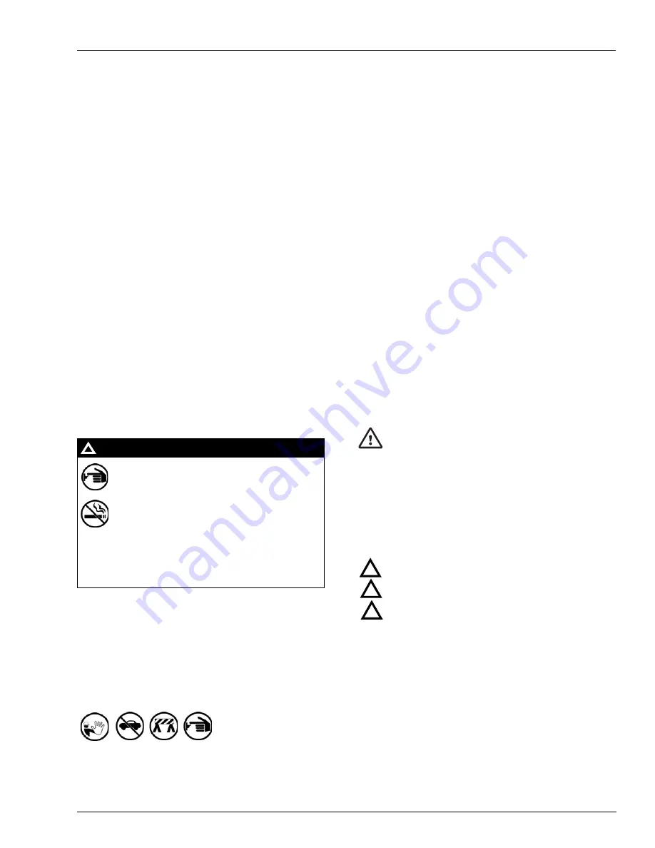
• An evacuation of all unauthorized persons and vehicles from 

the work area 

• Use of safety tape, cones or barricades at the affected unit(s)
• A total electrical shut-off of the affected unit(s)

Read the Manual

Read, understand and follow this manual and any other labels 
or related materials supplied with this equipment. If you do not 
understand a procedure, call the Technical Assistance Center 
(TAC) at 1-800-743-7501. It is imperative to your safety and the 
safety of others to understand the procedures before beginning 
work.

Follow the Regulations

Applicable information is available in National Fire Protection 
Association (NFPA) 30A; 

Code for Motor Fuel Dispensing 

Facilities and Repair Garages

, NFPA 70; 

National Electrical 

Code (NEC)

, Occupational Safety and Health Administration 

(OSHA) regulations and federal, state, and local codes. All 
these regulations must be followed. Failure to install, inspect, 
maintain or service this equipment in accordance with these 
codes, regulations and standards may lead to legal citations 
with penalties or affect the safe use and operation of the 
equipment.

Replacement Parts

Use only genuine Gilbarco replacement parts and retrofit kits on 
your pump/dispenser. Using parts other than genuine Gilbarco 
replacement parts could create a safety hazard and violate 
local regulations.

Safety Symbols and Warning Words

This section provides important information about warning 
symbols and boxes.

Alert Symbol 

This safety alert symbol is used in this manual and on 

warning labels to alert you to a precaution which must be 
followed to prevent potential personal safety hazards. Obey 
safety directives that follow this symbol to avoid possible injury 
or death.

Signal Words

These signal words used in this manual and on warning labels 
tell you the seriousness of particular safety hazards. The 
precautions below must be followed to prevent death, injury or 
damage to the equipment:

DANGER

:


Alerts you to a hazard or unsafe practice 

which will result in death or serious injury.

WARNING

: Alerts you to a hazard or unsafe practice 

that could result in death or serious injury. 

CAUTION

 with Alert symbol: Designates a hazard or 

unsafe practice which may result in minor injury.

CAUTION

 without Alert symbol: Designates a hazard or 

unsafe practice which may result in property or 
equipment damage.

Working With Fuels and Electrical Energy

Prevent Explosions and Fires

Fuels and their vapors will explode or burn, if ignited. Spilled or 
leaking fuels cause vapors. Even filling customer tanks will 
cause potentially dangerous vapors in the vicinity of the 
dispenser or island.

DEF is non-flammable. Therefore, explosion and fire safety 
warnings do not apply to DEF fluid lines.

!

!

!


Содержание FlexPay EPK ECIM RF

Страница 1: ...ors ASCs Table of Contents Topic Page Introduction 1 Important Safety Information 5 Before You Begin 7 Installing FlexPay EPP Kit 7 Installing SCR Kit 28 Required Tools and Materials Following tools a...

Страница 2: ...127B006 1 Optional Components Shipped Loose for Dispensers with Color Screen Option Quantity per Dispenser 12 Printed Circuit Assembly PCA RS 232 to Transistor Transistor Logic TTL Converter M07592A00...

Страница 3: ...MDE 4769 Personality Screen Change for Color Screen Update and or Upload Instructions Encore and Eclipse Applause Media System MDE 4784 FlexPay Encrypting PIN Pad EPP Start up and Service Manual Advan...

Страница 4: ...ns for Encore S E CIM December 2015 Introduction POS Point of Sale PPU Price per Unit SCR Secure Card Reader SP Secure Payment TAC Technical Assistance Center TRIND Transmitter Receiver in Dispenser T...

Страница 5: ...e of safety tape cones or barricades at the affected unit s A total electrical shut off of the affected unit s Read the Manual Read understand and follow this manual and any other labels or related ma...

Страница 6: ...mergency Personnel Compile the following information and inform emergency personnel Location of accident for example address front back of building and so on Nature of accident for example possible he...

Страница 7: ...site and dispenser for the upgrade proceed as follows 1 Inform the manager 2 Barricade the unit to be worked on 3 Remove power to the unit at the breaker panel Block off the unit from customers Follo...

Страница 8: ...of the soda button while pulling from the bottom of the soda buttons The grade select bases will remain in position Note Be careful not to dislodge the magnets Figure 1 Removing Grade Select Buttons G...

Страница 9: ...g FlexPay EPP Kit 7 Remove the five screws on the top row that hold the lower portion of the CIM assembly in place using a Phillips screwdriver Figure 3 Removing Lower Portion of E CIM Door 8 Disconne...

Страница 10: ...r CIM insert screws 1 2 inch and 1 4 inch and washers that hold the main display lens in place to facilitate the removal of the existing CIM assembly Figure 5 Removing Upper CIM Insert Screws and Wash...

Страница 11: ...reader and card reader bracket using a 1 4 inch nut driver Figure 7 Removing Card Reader and Card Reader Bracket Card Reader 12 Remove any other peripherals that are installed on the CIM assembly 13...

Страница 12: ...ved 15 Remove the screws that secure the CIM assembly Note Retain the screws for reuse Figure 9 Removing CIM Screws Removed 16 Remove the existing CIM assembly 17 Verify if the gasket on the CIM assem...

Страница 13: ...P Kit 18 Reinstall the three screws removed in step 13 on page 11 which secure the PPU board bracket in place Figure 11 Installing PPU Board Bracket 19 Reinstall the two upper CIM insert screws and wa...

Страница 14: ...moved in step 8 on page 9 Figure 13 Installing Door Node 21 Inspect the bosses on the door before installing the card reader and display Use M14757B001 Screws if the door has metal bosses and use Q116...

Страница 15: ...screws as determined in step 21 on page 14 Figure 15 Installing Monochrome Display Monochrome Display 23 Reconnect the softkey cable to the Softkey keypad 24 Connect the new call button cable that is...

Страница 16: ...FlexPay EPP Kit 26 Reconnect the cables that connect to the card reader Figure 17 Connecting Cables to Card Reader 27 Reinstall the five screws to secure the PPU board in place Figure 18 Reinstalling...

Страница 17: ...Reinstall the grade select buttons Ensure that these are in the appropriate locations Figure 20 Installing Grade Select Buttons Grade Select Buttons Installed 30 Repeat steps 1 on page 7 through 29 fo...

Страница 18: ...ome units proceed as follows 1 Connect the FlexPay EPP cable to the FlexPay EPP and the other end to P3101 SmartPad port on the CRIND Control Node CCN Connect the FlexPay EPP cable to P3102 on the CCN...

Страница 19: ...7592A001 PCA Board J202 of the Serial Programming Port Cable M00719A004 to the P202 COM1 port J227 of the COM2 Cable M07749A001 to the P227 COM2 port J302A of the RS 232 24 V Power Cable M07746A001 to...

Страница 20: ...n Instructions for Encore S E CIM December 2015 Installing FlexPay EPP Kit 3 Connect J302X of the M07746A001 Cable to P302X on the color CRIND Interface Board M06187A002 Figure 24 Connecting Power Sup...

Страница 21: ...ns for Encore S E CIM December 2015 Page 21 Installing FlexPay EPP Kit 4 Connect the M07749A001 Cable from the P227 COM2 port on M07592A001 PCA Board to CN27 on the 10 4 inch CPU Board M03377A001 Figu...

Страница 22: ...ion Instructions for Encore S E CIM December 2015 Installing FlexPay EPP Kit 5 Connect the M00719A004 Cable from the P202 COM1 port on M07592A001 PCA Board to CN2 on the 10 4 inch CPU board Figure 26...

Страница 23: ...exPay EPP cables from the rear of the keypads to the appropriate SmartPad ports on the M07592A001 PCA Board P3101 for side B and P3102 for side A Figure 27 Connecting FlexPay EPP Cables to SmartPad Po...

Страница 24: ...lexPay EPP Kit Upgrading Flash Card on Color Screen CRIND CPU Assembly To upgrade the flash card on the color screen CRIND CPU assembly proceed as follows 1 Release the color screen CRIND CPU assembly...

Страница 25: ...emove the existing flash card and insert the CRIND Software Flash Card M07743K001 which contains the upgraded software see Figure 29 Note Ensure that you do not bend the pins when you install the flas...

Страница 26: ...een Update and or Upload Instructions 7 Proceed to Completing Installation Completing Installation To complete the installation proceed as follows 1 Restore power to the unit 2 Purge memory 3 When the...

Страница 27: ...r Encore S E CIM December 2015 Page 27 Installing FlexPay EPP Kit 7 Check if debit transactions are accepted using the newly installed FlexPay EPP Figure 31 Encore S E CIM Unit with FlexPay EPP Instal...

Страница 28: ...m the existing standard card reader 2 Remove the four screws that secure the card reader assembly to the dispenser using a 1 4 inch nut driver Retain the screws for reassembly 3 Pull the card reader a...

Страница 29: ...gasket is laid over the card reader snout first then the card reader is inserted into the card reader opening on the door In this application the card reader becomes your insertion tool Figure 33 New...

Страница 30: ...k of MasterCard International Inc GOLDSM is a service mark of Gilbarco Inc Phillips is a registered trademark of the Phillips Screw Company UL is a registered trademark of Underwriters Laboratories In...

Отзывы: