


System Appearance
- 16 -
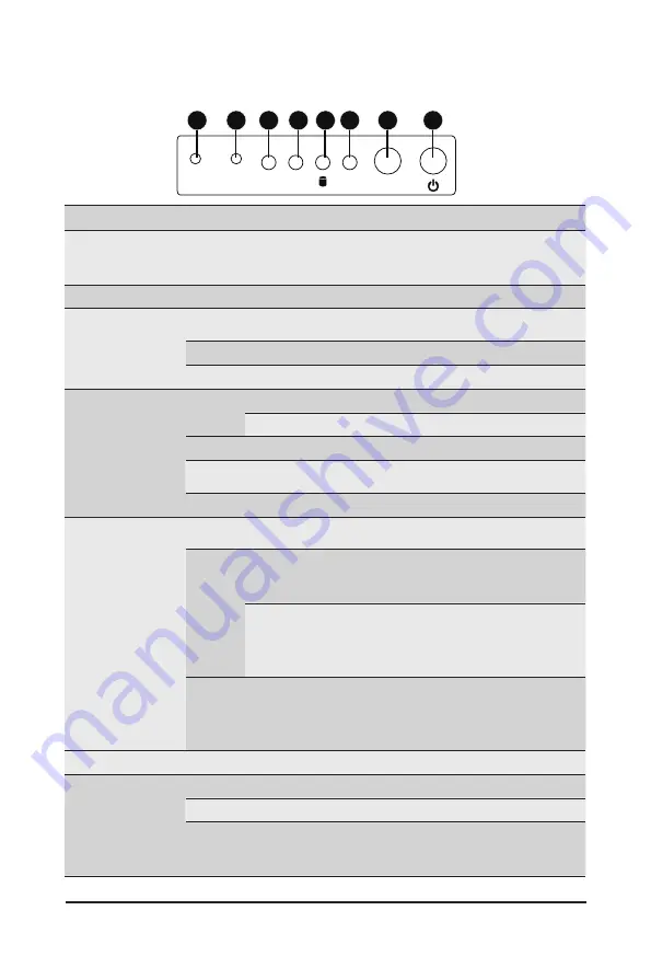
2-3 Front Panel LED and Buttons
L2
SYS
ID
L1
RST
NMI
8
7
6
5
4
3
2
1
No. Name
Color
Status
Description
1.
NMI button
Press the button server generates a NMI to the processor
if the multiple-bit ECC errors occur, which effectively halt
the server.
2.
Reset Button
Press the button to reset the system.
3/4.
LAN 1/2
Active/Link
LEDs
Green
Solid
On
Link between system and network or no access.
Green
Blink
Data trasmission or receiving is occuring
N/A
Off
No data transmission or receiving is occuring
5.
HDD Status
LED
Green
On
HDD locate
Blink
HDD access
Amber
On
HDD fault
Green/
Amber
Blink
HDD rebuilding
N/A
Off
No HDD access or no HDD fault.
6.
System
Status LED
Green
Solid
On
System is operating normally.
Amber
Solid
On
Critical condition, may indicate:
System fan failure
System temperature
Blink
Non-critical condition, may indicate:
Redundant power module failure
Temperature and voltage issue
Chassis intrusion
N/A
Off
System is not ready, may indicate:
POST error
NMI error
Processor or terminator missing
7.
ID Button
Press the button to activate system identification
8.
Power button
with LED
Green
On
System is powered on
Green
Blink
System is in ACPI S1 state (sleep mode)
N/A
Off
•
System is not powered on or in ACPI S5 state
(power off)
•
System is in ACPI S4 state (hibernate mode)
Содержание LGA3647
Страница 1: ...R161 340 Dual LGA3647 sockets motherboard for Intel Scalable Family Processors Service Guide Rev 1 0 ...
Страница 20: ...System Appearance 20 This page intentionally left blank ...
Страница 25: ... 25 System Hardware Installation 1 4 3 2 5 6 ...
Страница 34: ...System Hardware Installation 34 System Fan Cable On Board SATA to HDD Back Plane Board Cable ...
Страница 58: ...BIOS Setup 58 5 2 11 Intel R I210 Gigabit Network Connection ...
Страница 60: ...BIOS Setup 60 5 2 12 VLAN Configuration ...
Страница 64: ...BIOS Setup 64 5 3 1 Processor Configuration ...


