background image

Hardware Installation

- 14 -

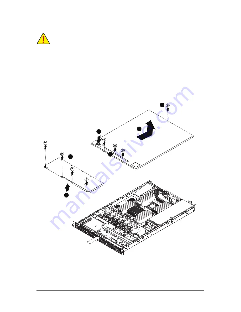
2-1  Removing System Cover

Before you remove or install the system cover

• 

Make sure the system is not turned on or connected to AC power.

Follow these instructions to remove the system cover:

1.  Loosen and remove the screws securing the back cover.
2.  Push down the indentation located at the side of the back chassis
3.  Slide the cover horizontally to the back using the traction pad and remove the back cover in the 

direction of the arrow.

4.  Loosen and remove the screws securing the front top cover.
5.  Remove the front top cover from the system.

1

4

2

1

3

5

Содержание GS-R12PE

Страница 1: ...GS R12PE GS R12PE1 Dual LGA2011 socket motherboard for Intel Xeon series processors Service Guide Rev 1 0 ...

Страница 2: ...BYTE without prior notice No part of this manual may be reproduced copied translated transmitted or published in any form or by any means without GIGABYTE s prior written permission Documentation Classifications Inordertoassistintheuseofthisproduct GIGABYTEprovidesthefollowingtypesofdocumentations For quick set up of the product read the Quick Installation Guide included with the product For detai...

Страница 3: ... NOT be covered in this generic service guide In suchcases please contact your regional offices or the responsible personnel channel to provide youwith further technical details 2 Please note WHEN ORDERING SPARE PARTS you should check the most up to date informationavailable on your regional web or channel For whatever reason if a part num ber change is made it will not be noted in the printed Ser...

Страница 4: ... 2 4 2 Installing a Memory 19 2 4 3 DIMM Population Table 20 2 6 Installing the PCI Expansion Card 21 2 7 Installing the Hard Disk Drive 22 2 7 1 Hard Disk Drive Security Lock 23 2 8 Replacing the Back Plane Board 24 2 9 Replacing the Power Supply 25 2 10 Replacing the FAN Assemblly 26 Chapter 3 System Appearance 27 3 1 Front View 27 3 2 Rear View 28 3 3 Front Panel LED and Buttons 29 3 4 Rear Sys...

Страница 5: ... 5 3 1 North Bridge Configuration 56 5 3 1 1 IOH Configuration 57 5 3 1 2 DIMM Information 60 5 3 2 South Bridge Configuration 62 5 3 3 ME Subsystem 63 5 4 Security Menu 64 5 5 Server Management Menu 65 5 5 1 System Information 66 5 5 2 BMC LAN Configuration 67 5 5 3 System Event Log 68 5 6 Boot Option Menu 69 5 7 Boot Manager 70 5 8 Exit Menu 71 5 9 BIOS Beep Codes 72 5 9 1 PEI Beep Codes 72 5 9 ...

Страница 6: ... R12PE1 Driver CD The box contents above are for reference only and the actual items shall depend on the product package you obtain The box contents are subject to change without notice The motherboard image is for reference only ...

Страница 7: ...o not block or cover these openings Make sure youprovide adequate space around the system for ventilation when you set up your work area Never insertobjects of any kind into the ventilation openings To avoid electrical shock always unplug all power cables and modem cables from the wall outletsbefore removing covers Allow the product to cool before removing covers or touching internal components Pr...

Страница 8: ...undesired opera tion Canadian Department of Communications Compliance Statement This digital apparatus does not exceed the Class A limits for radio noise emissions from digitalapparatus as set out in the radio interference regulations of Industry Canada Le present appareil numerique n emet pas de bruits radioelectriques depassant les limites applicables auxappareils numeriques de Classe A prescrit...

Страница 9: ...he waste collection centers for activation of the treatment collection recycling and disposal procedure The separate collection and recycling of your waste equipment at the time of disposal will help to conserve natural resources and ensure that it is recycled in a manner that protects human health and the environment For more information about where you can drop off your waste equipment for recyc...

Страница 10: ... dry and first touch a metal object to eliminate static electricity Prior to installing the motherboard please have it on top of an antistatic pad or within an electrostatic shielding container Before unplugging the power supply cable from the motherboard make sure the power sup ply has been turned off Before turning on the power make sure the power supply voltage has been set according to the loc...

Страница 11: ...ernet LAN ports GS R12PE Expansion Slot Low Profile 1 x PCI Express x16 slot running at Gen3 x16 1 x PCI Express x16 slot running at Gen3 x8 Onboard Graphics ASPEED AST2300 supports 64MB VRAM Mass Storage 4 x 3 5 Hot Swap SATA SAS HDDs Support for Intel IRST SATA RAID 0 RAID 1 RAID 10 System Fans 6 x 40x40x56mm 16000rpm USB Up to 4 USB 2 0 1 1 ports 2 on the back panel 2 via the USB brackets conne...

Страница 12: ...r ASPEED AST2300 Hardware Monitor System voltage detection CPU System temperature detection CPU System fan speed detection CPU System fan speed control Whether the CPU system fan speed control function is supported will depend on the CPU system cooler you install BIOS 1 x 64 Mbit flash AMI BIOS Environment Ambient Temperature Relative Humidity Operating Temperature 5oC to 35oC Non operating Temper...

Страница 13: ...both sides of the CPU and alignment keys on the CPU socket Apply an even and thin layer of thermal grease on the surface of the CPU Do not turn on the computer if the CPU cooler is not installed otherwise overheating and dam age of the CPU may occur Set the CPU host frequency in accordance with the CPU specifications It is not recommended that the system bus frequency be set beyond hardware specif...

Страница 14: ...to remove the system cover 1 Loosen and remove the screws securing the back cover 2 Push down the indentation located at the side of the back chassis 3 Slide the cover horizontally to the back using the traction pad and remove the back cover in the direction of the arrow 4 Loosen and remove the screws securing the front top cover 5 Remove the front top cover from the system 1 4 2 1 3 5 ...

Страница 15: ...d Installing the Fan Duct Follow these instructions to remove install the fan duct 1 Lift up to remove the fan duct 2 To install the fan duct align the fan duct with the guiding groove Push down the fan duct into chassis until its firmly seats ...

Страница 16: ...tall the CPU Make sure that the motherboard supports the CPU Always turn off the computer and unplug the power cord from the power outlet before installing the CPU to prevent hardware damage Unplug all cables from the power outlets Disconnect all telecommunication cables from their ports Place the system unit on a flat and stable surface Open the system according to the instructions WARNING Failur...

Страница 17: ... install the heat sinks 1 Apply thermal compound evenly on the top of the CPU Remove the protective cover from the underside of the heat sink 2 Place the heat sink s on top of the CPU and tighten the four positioning screws 1 2 2 4 Installing the Heat Sink ...

Страница 18: ...DDR3_P1_G0 DDR3_P1_G1 DDR3_P1_G2 For secondary CPU Channel 4 DDR3_P0_D0 DDR3_P0_D1 DDR3_P0_D2 For pimary CPU DDR3_P1_H0 DDR3_P1_H1 DDR3_P1_H2 For secondary CPU 2 5 Installing the Memory Read the following guidelines before you begin to install the memory Make sure that the motherboard supports the memory It is recommended that memory of the same capacity brand speed and chips be used Always turn o...

Страница 19: ...into the DIMM slot and push it down 2 Close the plastic clip at both edges of the DIMM slots to lock the DIMM module 3 Reverse the installation steps when you wish to remove the DIMM module 2 2 1 Due to CPU limitations read the following guidelines before installing the memory in Four Channel mode 1 Four Channel mode cannot be enabled if only one DDR3 memory module is installed 2 When enabling Fou...

Страница 20: ...0 n a 800 1066 1066 1333 1066 1333 1600 1066 1333 1066 1333 1600 n a 800 1066 800 1066 800 800 n a n a 800 1066 800 800 n a n a 2 4 3 DIMM Population Table 3 Slots Per Channel UDIMM 1DPC 2DPC 1 35V 1 5V 1 35V 1 5V n a 1066 1333 n a 1066 1333 n a 1066 1333 n a 1066 1333 n a 1066 1333 n a 1066 1333 1066 1066 1333 1066 1066 1333 1066 1066 1333 1066 1066 1333 3 Slots Per Channel LRDIMM 1DPC and 2DPC 3...

Страница 21: ...lure to observe these warnings could result in personal injury or damage to equipment The PCI riser assembly does not include a riser card or any cabling as standard To install a PCI card a riser card must be installed Follow these instructions to PCI Expansion card 1 Loosen the riser bracket screwsand lift the riser bracket slightly then pull it out from the server chassis 2 Orient the PCI card w...

Страница 22: ...ake sure that the HDD is connected to the HDD connector on the backplane Follow these instructions to Hard disk drive 1 Press the release button 2 Pull the locking lever to remove the HDD tray 3 Slide hard disk into blank 4 Secure the hard drive to the tray with four 4 screws as shown Do not over tighten thescrews Slide the blank into the bay until it locks into place 5 Engage the HDD Security Loc...

Страница 23: ... Lock The HDD bays incorporate a security screw to prevent accidental HDD release To engage the lock turn the security screw clock wise toward the Lock symbol To disengage the lock turn the security screw counter clock wise toward the Unlock symbol as shown ...

Страница 24: ...se instructions to replace the back plane board 1 Remove the chassis cover See Removing the System Cover on page 14 2 Loosen and remove the screws securing the back plane boardas illustration arrow show 3 Replace the back plane board into chassis and secure with screws 1 2 ...

Страница 25: ...power cables 2 Pull up the power supply handle and press the retaining clip on the right side of the power supply along the direction of the arrow At the same time pull out the power supply by using its handle 3 Insert the replacement power supply firmly into the chassis Connect the AC power cord to the re placement power supply ...

Страница 26: ...emblly Follow these instructions to replace the fan assembly 1 Remove thefan assemble pulling the rear edge in the direction of the arrow 2 Lift up the fan assembly from the chassis 3 Reverse the previous steps to install the replacement fan assembly 1 2 ...

Страница 27: ... 27 Hardware Installation Chapter 3 System Appearance 3 1 Front View No Decription 1 HDD bays 2 USB ports 3 Front Panel LEDs and buttons 1 2 3 ...

Страница 28: ... Serial port 4 RJ 45 LAN ports 5 Management LAN port 6 USB ports 7 10G LAN ports 8 PCI Express card bays No Decription 1 Power modules 2 VGA port 3 Serial port 4 RJ 45 LAN ports 5 Management LAN port 6 USB ports 7 PCI Express card bays GS R12PE GS R12PE1 1 8 2 3 4 5 6 7 1 7 2 3 4 5 6 ...

Страница 29: ...e 2 ID button and LED Blue On System identification is active N A Off System identification is disabled 3 System Status LED Green On Running or normal peration Amber On There s at least one sensor that has critical alert N A Off System not ready 4 HDD Status LED Green On HDD access N A Off Idle 5 LAN 2 LED Green On Link between system and network or no access Green Blink Network access 6 LAN 1 LED...

Страница 30: ... receiving is occurring 3 Activity LED Green Blink Data transmission or receiving is occurring On Link between system and network or no access Off No data transmission or receiving is occurring 4 Connection Speed LED Green On Linking at 100 Mbps data rate Blink Identify 100 Mbps data rate N A Off Linking at 10 Mbps data rate 5 Connection Speed LED Yellow On Linking at 1 Gbps data rate Blink Identi...

Страница 31: ...ply LEDs Power Supply LED Power Supply Status Color Power Switch On Blinking Green g Red gGreen Normal State Green Power Switch Off Green gRed Blinking gGreen Standby AC In Only 5VSB output Blinking Green Power Fail Red Fan Fail Blinking Red ...

Страница 32: ...ve On Off Hard disk drive is present and active Blink Off Location Blink Blink 4 Hz RAID failed HDD remove On Hard disk drive is rebuilding On Blink Blink 1 Hz SCU RAID Hard disk drive is not present Off Off Hard disk drive is present but not active On Off Hard disk drive is present and active Blink Off Location Blink Blink 4 Hz RAID failed On Hard disk drive is rebuilding Blink Blink 1 Hz When HD...

Страница 33: ...er 4 Motherboard Components 4 1 GA 7PPSH GA 7PPSH2 Motherboard Components 1 2 3 4 6 5 7 8 9 10 11 12 13 16 17 18 19 20 21 30 29 28 27 26 25 51 52 53 54 55 56 14 31 22 23 15 24 32 33 34 35 36 37 38 39 41 40 42 43 44 45 46 47 48 49 50 ...

Страница 34: ...primary CPU 19 DDR3_P0_A2 Channel 1 slot 2 for primary CPU 20 DDR3_P0_A1 Channel 1 slot 1 for primary CPU 21 DDR3_P0_A0 Channel 1 slot 0 for primary CPU 22 PWR_DET1 PMBus connector 23 P12V_AUX1 8 pin power connector 24 CPU0 Intel LGA2011 socket Primary CPU 25 DDR3_P0_D2 Channel 4 slot 2 for primary CPU 26 DDR3_P0_D1 Channel 4 slot 1 for primary CPU 27 DDR3_P0_D0 Channel 4 slot 0 for primary CPU 28...

Страница 35: ...CI E slot 2 Gen3 x16 slot x8 bus 49 BAT1 Battery socket 50 PCI E_1 PCI E slot 2 Gen3 x16 slot x16 bus 51 DDR3_P1_E0 Channel 1 slot 0 for secondary CPU 52 DDR3_P1_E1 Channel 1 slot 1 for secondary CPU 53 DDR3_P1_E2 Channel 1 slot 2 for secondary CPU 54 DDR3_P1_F0 Channel 2 slot 0 for secondary CPU 55 DDR3_P1_F1 Channel 2 slot 1 for secondary CPU 56 DDR3_P1_F2 Channel 2 slot 2 for secondary CPU ...

Страница 36: ...n Default setting 2 3 Close Enable BIOS write protect function 2 FLASH_DP1 Flash Descriptor Security Jumper 1 2 Close Flash Descriptor Security Overridden 2 3 Close Flash Descriptor Security in effect Default setting 3 SSB_ME1 ME enable disable Jumper 1 2 Close Normal operation Default setting 2 3 Close Disable ME function 1 2 3 4 6 7 5 ...

Страница 37: ...CR1 BIOS Recovery Jumper 1 2 Close Normal operation Default setting 2 3 Close BIOS recovery mode 6 PASSWORD1 Skip Supervisor password Jumper 1 2 Close Normal operation Default setting 2 3 Close Skip supervisor password 7 BMC_FRB1 Force to Stop FRB3 Timer Jumper 1 2 Close Normal operation Default setting 2 3 Close Force to Stop FRB3 Timer ...

Страница 38: ...BIOS To flash the BIOS do it with caution Inadequate BIOS flashing may result in system malfunction It is recommended that you not alter the default settings unless you need to to prevent system instability or other unexpected results Inadequately altering the settings may result in system s failure to boot If this occurs try to clear the CMOS values and reset the board to default values Refer to ...

Страница 39: ...upervisor password allows you to restrict access to the system and BIOS Setup A supervisor password allows you to make changes in BIOS Setup A user password only allows you to view the BIOS settings but not to make changes Server Management Server additional features enabled disabled setup menus Boot Options This setup page provides items for configuration of boot sequence Boot Manager This setup ...

Страница 40: ...isplayed on the bottom line of the Main Menu Submenu Help While in a submenu press F1 to display a help screen General Help of function keys available for the menu Press Esc to exit the help screen Help for each item is in the Item Help block on the right side of the submenu When the system is not stable as usual select the Load Default Values item to set your system to its defaults The BIOS Setup...

Страница 41: ... Information Total Memory Determines how much total memory is present during the POST System Date Set the date following the weekday month day year format System Time Set the system time following the hour minute second format Access Level Display the current accessing level information ...

Страница 42: ... Setup 42 5 2 Advanced Menu The Advanced menu display submenu options for configuring the function of various hardware components Select a submenu item then press Enter to access the related submenu screen ...

Страница 43: ... Optional Enable Disable Onboard LAN controller Options available Enabled Disabled Default setting is Enabled LAN1 2 Option ROM Enable Disable onboard LAN1 device and initialize device expansion ROM Options available Enabled Disabled Default setting for LAN 1 Option ROM is Enabled Default setting for LAN 2 Option ROM are Disabled LAN3 4 Option ROM Optional Enable Disable onboard LAN1 device and in...

Страница 44: ... error PERR is generated and is routed to NMI Options available Enabled Disabled Default setting is Enabled SERR Generation When this item is set to enabled PCI bus system error SERR is generated and is routed to NMI Options available Enabled Disabled Default setting is Enabled ...

Страница 45: ... TPM State Note Select Enabled to activate TPM State function Options available Enabled Disabled Default setting is Enabled Pending Operation Note Determine the action when operation is pending Options available None Default setting is None Current Status Information Display current TPM status information Note This item appears when the TPM module is attached ...

Страница 46: ...BIOS Setup 46 5 2 3 CPU Configuration ...

Страница 47: ... 47 BIOS Setup ...

Страница 48: ...Display the current installed CPU speed 64 bit Display the supported infprmation of installed CPU Hyper threading The Intel Hyper Threading Technology allows a single processor to execute two or more separate threads concurrently When hyper threading is enabled multi threaded software applications can execute their threads thereby improving performance Options available Enabled Disabled Default se...

Страница 49: ...T Enhanced Intel SpeedStep Technology Conventional Intel SpeedStep Technology switches both voltage and frequency in tandem between high and low levels in response to processor load Options available Enabled Disabled Default setting is Enabled Turbo Mode When this feature is enabled the processor can dynamically overclock one or two of its four processing cores to improve performance with applicat...

Страница 50: ...BIOS Setup 50 5 2 4 Runtime Error Logging Runtime Error Logging Support Enable Disable Runtime error logging support Options available Enabled Disabled Default setting is Enabled ...

Страница 51: ...is disabled and cannot be access the RAID setup utility at boot time Options available IDE RAID AHCI Disabled Default setting is AHCI Mode SATA Port 0 1 2 3 4 5 Displays the installed HDD devices information Press Enter to view detail information of the installed HDD devices Serial ATA Controller 0 1 Determine the onboard SATA controller mode Compatible SATA and PATA drives are auto detected and p...

Страница 52: ...led Disabled Default setting is Enabled Onboard SAS oprom Enable Disable onboard SAS option ROM Options available Enabled Disabled Default setting is Enabled SAS Configuration Note Device 0 1 2 3 4 5 6 7 Displays the installed HDD devices information Note This item will appear when the SAS device is attached ...

Страница 53: ... 53 BIOS Setup 5 2 6 Serial Port Console Redirection ...

Страница 54: ... 1 s the data bits is odd Mark parity bit is always 1 Space Parity bit is always 0 Mark and Space Parity do not allow for error detection Options available None Even Odd Mark Space Default setting is None Stop Bits Stop bits indicate the end of a serial data packet A start bit indicates the beginning The standard setting is 1 stop bit Communication with slow devices may require more than 1 stop bi...

Страница 55: ...BIOS Setup 5 3 Chipset Menu The Chipset menu display submenu options for configuring the function of North Bridge and South Bridge Select a submenu item then press Enter to access the related submenu screen ...

Страница 56: ...BIOS Setup 56 5 3 1 North Bridge Configuration ...

Страница 57: ... 57 BIOS Setup 5 3 1 1 IOH Configuration ...

Страница 58: ...ting is Disabled IOH 0 1 PCIe port Bifurcation Control IOU1 PCIe Port Options available x4x4 x8 PORT 1A Link Speed Options available Gen1 Gen2 Gen3 PORT 1B Link Speed Options available Gen1 Gen2 Gen3 IOU2 PCIe Port Options available x4x4x4x4 x4x4x8 x8x4x4 x8x8 x16 PORT 2A Link Speed Options available Gen1 Gen2 Gen3 PORT 2C Link Speed Options available Gen1 Gen2 Gen3 PORT 2D Link Speed Only for IOH...

Страница 59: ...wo identical redundant copies of all data in memory When set to Lockstep mode the motherboard uses two areas of memory to run the same set of operations in parallel When set to Sparing mode a preset threshold of coorectable errors is used to trigger fail over The spare memory is put online and used as active memory in place of the failed memory Options available Indpendent Mirroring Lockstep Spari...

Страница 60: ...BIOS Setup 60 5 3 1 2 DIMM Information ...

Страница 61: ...atus CPU Socket 1 DDR3_P1_E0 DDR3_P1_E1 DDR3_P1_E2 DDR3_P1_F0 DDR3_P1_F1 DDR3_P1_F2 DDR3_P1_G0 DDR3_P1_G1 DDR3_P1_G2 DDR3_P1_H0 DDR3_P1_H1 DDR3_P1_H2 Status The size of memory installed on each of the DDR3 slots To clear ECC Flag To clear ECC Flag When DDR3 Channel is maskdoff after ECC multibit errors it s required to clear ECC flag to make masked off channels be available Options available None ...

Страница 62: ...led Restore on AC Power Loss Note Defines the power state to resume to after a sys tem shutdown that is due to an interruption in AC power When set to Last State the system will return to the active power state prior to shutdown When set to Stay Off the system remains off after power shutdown Options available Last State Stay Off Power On The default setting depends on the BMC setting Note When th...

Страница 63: ... 63 BIOS Setup 5 3 3 ME Subsystem ME Subsystem Configuration Enable Disable ME subsystem configuration Options available Enabled Disabled Default setting is Enabled ...

Страница 64: ...he Setup menus To enable or disable this field a Administrator Password must first be set A user can only access and modify the System Time System Date and Set User Password fields Set Administrator Password Press Enter to configure the Administrator password Set User Password Press Enter to configure the user password 5 4 Security Menu The Security menu allows you to safeguard and protect the sys...

Страница 65: ...n BMC LAN Configuration BMC LAN Configuration Press Enter to access the related submenu System Event Log System Event Log Configuration Press Enter to access the related submenu Select NCSI and Dedicated LAN Switch NCSI and dedicated LAN and send KCS command Options available Mode2 NSCI Mode1 Dedicated Default setting is Mode1 Dedicated ...

Страница 66: ...IOS Setup 66 5 5 1 System Information The System Management submenu is a simple display page for BMC information of firmware version SOR version and FRU version Items on this window are non configurable ...

Страница 67: ...k parameters during BIOS phase Options available Static Dynamic Do Nothing Default setting is Do Nothing IP Address Display IP Address information Subnet Mask Display Subnet Mask information Please note that the IP address must be in three digitals for example 192 168 000 001 Default Gateway Address Display Default Gateway Address information 5 5 2 BMC LAN Configuration ...

Страница 68: ...BIOS Setup 68 5 5 3 System Event Log Erasing Settings Erase SEL Choose options fro erasing SEL Options available No Yes On next reset Yes On every reset Default setting is No ...

Страница 69: ... Configuration Bootup NumLock State Enable or Disable Bootup NumLock function Options available On Off Default setting is On Quiet Boot Enables or disables showing the logo during POST Options available Enabled Disabled Default setting is Enabled Interrupt 19 Capture Interrupt 19 is the software interrupt that handles the boot disk function When enabled this BIOS fea ture allows the ROM BIOS of th...

Страница 70: ...ot manager menu allows you to specify the boot up drive BIOS setup will display an error message if the legacy drive s specified is not bootable Boot Override UEFI Built in EFI Shell Press Enter to configure the device as the boot up drive ...

Страница 71: ...ptions available Yes No Save Changes Saves changes made in the BIOS setup Options available Yes No Discard Changes Discards all changes made in the BIOS setup Options available Yes No Load Default Values Loads the default settings for all BIOS setup parameters Setup Defaults are quite demanding in terms of resources consumption If you are using low speed memory chips or other kinds of low performa...

Страница 72: ... found 3 DXE Core Firmware Volume was not found 4 Recovery failed 4 S3 Resume failed 7 Reset PPI is not available of Beeps Description 1 Invalid password 4 Some of the Architectural Protocols are not available 5 No Console Output Devices are found 5 No Console Input Devices are found 6 Flash update is failed 7 Reset protocol is not available 8 Platform PCI resource requirements cannot be met 5 9 2...

Страница 73: ... becomes corrupt the boot block can be used to restore the BIOS to a working state To restore your BIOS please follow the instructions listed below Recovery Instruction 1 Change xxx ROM to flashabl rom 2 Copy flashabl rom and AFUDOS exe to USB diskette 3 Setting BIOS Recovery jump to enabled status BIOS Recovery Jumper ...

Страница 74: ...BIOS Setup 74 4 Boot into BIOS recovery 5 Run Proceed with flash update 6 BIOS updated ...

Отзывы: