


- 7 -
English
Step 1: Install Memory Module(s)
Place i-RAM card on an anti-static pad. The DIMM socket
has a notch, so the memory module can only fit in one
direction. Push the clips at either end of the DIMM socket
outwards to the open position. Insert the memory module into
the DIMM socket. Then push it down until the retaining clips
snap into place (Figure 1).
We recommend slotting memory modules from the top socket.
Step 2: Install i-RAM
Select a free PCI slot and remove the screw and slot bracket.
Press the i-RAM card firmly into the slot and replace the
screw to secure the slot bracket of the i-RAM card. (Figure 2)
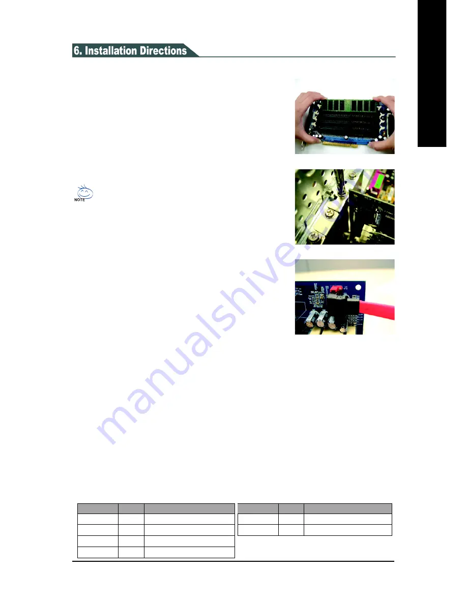
Step 3: Connect SATA Cable
Attach one end of the SATA interface cable to the SATA
connector on the i-RAM card (Figure 3). Locate an available
SATA connector on your motherboard and plug the other end
of the SATA interface cable into the SATA connector.
Figure 1
Please read the following installation directions before using i-RAM:
Figure 3
LEDs Information:
The LEDs in the top right of the battery holder provide the following information:
To remove the memory module, support the memory module with your
fingers while spreading the clips. This prevents the memory module from
being damaged when it pops out.
Figure 2
Step 4: Configure System BIOS
At system startup, enter system BIOS when prompted. Read the motherboard or system
documentation and assure that the motherboard SATA port connecting to i-RAM is enabled.
Finally, make sure i-RAM has been detected as a normal hard drive by system BIOS.
Step 5: Format i-RAM
In order for i-RAM to be visible in your operating system, it must be formatted. You can format
i-RAM using FDISK, Windows Disk Management or other third-party tools.
You are now ready to use i-RAM as a normal hard drive.
LED
Color
Description
PHY_READY
Blue
i-RAM is correctly detected
HD_LED
Blue
i-RAM is writing or reading data
3VDUAL
Yellow
i-RAM is powered by motherboard
CHARGING
Yellow The battery is being charged
LED
Color
Description
FULL
Green
The battery is at full charge
FAULT
Red
Battery malfunctions
Содержание GC-RAMDISK
Страница 2: ...RAMDISK July 29 2005 GC RAMDISK...


