Gigabyte GA-7GEWH-RH Скачать руководство пользователя страница 10

1 0

Hardware Installation Process

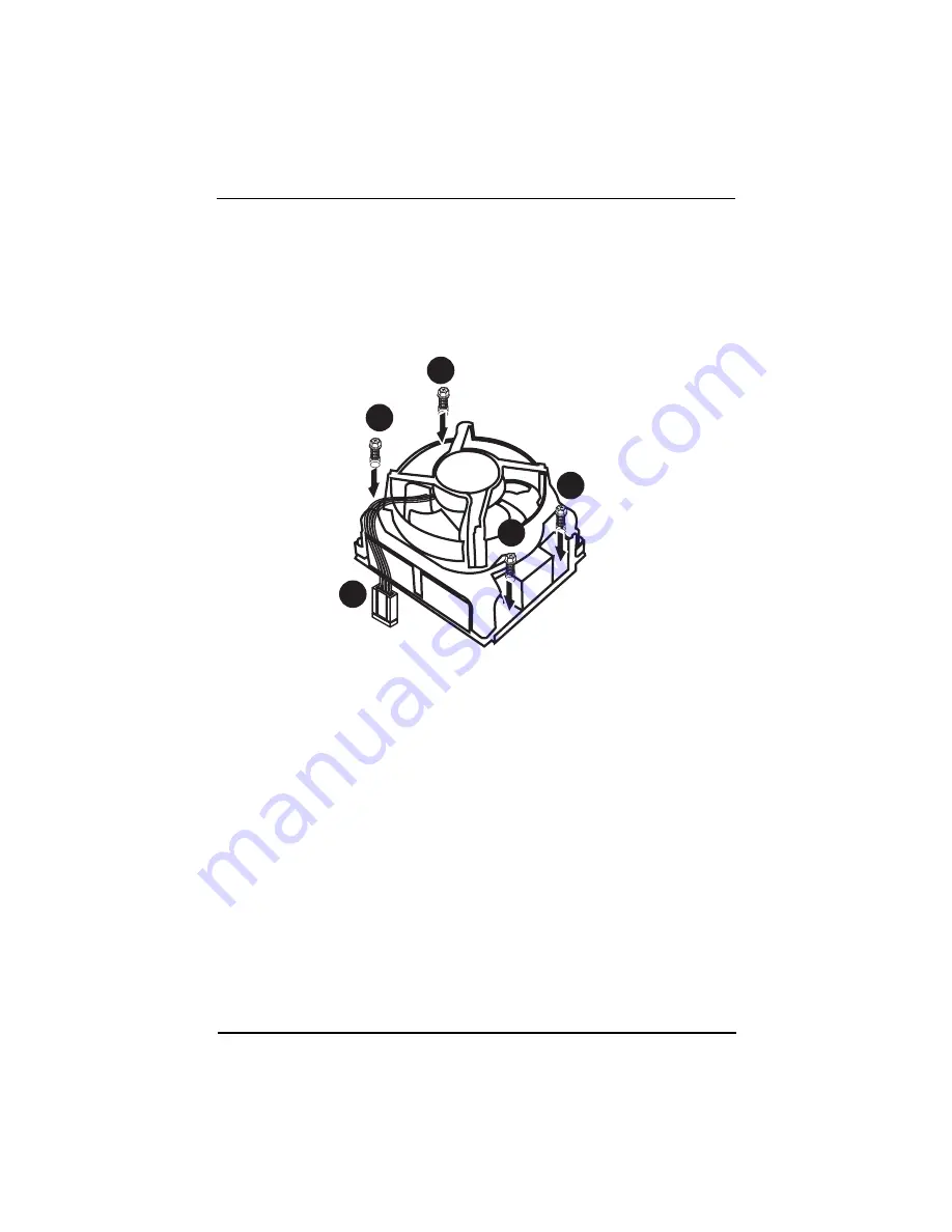
2.1.2. Installing Heat Sink

Step 1 Attach the  heat sink clip to the processor socket.
Step 2 Place the cooling fan on the heat sink.
Step 3 Secure the cooing fan with screws.
Step 4 Connect processor fan can cable to the processor fanconnector

1

1

1

1

2

Содержание GA-7GEWH-RH

Страница 1: ...The WEEE marking on the product indicates this product must not be disposed of with user s other household waste and must be handed over to a designated collection point for the recycling of waste ele...

Страница 2: ...1 2 Installing Heat Sink 10 2 2 Installing memory modules 11 2 3 Connect ribbon cables cabinet wires and power supply 13 2 3 1 I O Back Panel Introduction 13 2 4 Connectors Introduction 16 2 5 Jumper...

Страница 3: ...rial ATA cable x 6 IDE ATA100 cable x 1 Floppy cable x 1 I O Shield Kit CD for motherboard driver utility Power cable x 4 GA 7GEWH RH user s manual SAS cable x 2 Item Checklist The items listed above...

Страница 4: ...installation of the motherboard or any hardware please first carefully read the information in the provided manual 3 Before using the product please verify that all cables and power connectors are co...

Страница 5: ...ully Buffered DIMM FBD 533 667MHz y Support 512MB 1GB 2GB and 4GB memory I O Control y ITE Super I O Expansion Slots y 1 PCI slots 32 Bit 33MHz 5V y 2 PCI X slots 64 Bit 66 133MHz y 1 PCI Express x16...

Страница 6: ...ture Values viewing y CPU Power System Fan Revolution Detect y CPU shutdown when overheat y System Voltage Detect y Support basicASF remote transaction through CSABus with hardwarecircuit BIOS y Phoen...

Страница 7: ...tor 47 DIMMC1 16 SATA0 cable connector 48 DIMMC2 17 SATA 1cable connector 49 DIMMD1 18 SATA2 cable connector 50 DIMMD2 19 SATA3 cable connector 51 USB LAN Ports 20 SATA4 cable connector 52 USB LAN Por...

Страница 8: ...8 Introduction 2 1 3 4 5 6 7 9 10 8 12 11 13 14 15 22 23 24 25 26 27 29 30 28 33 31 32 34 35 36 37 39 40 38 42 41 52 51 53 54 55 56 57 59 60 58 16 21 19 17 20 18 61 62 63 64 434445 4647 49 50 48...

Страница 9: ...sure the CPU type is supported by the motherboard 5 If you do not match the CPU socket Pin 1 and CPU cut edge well it will cause improperinstallation Pleasechangetheinsertorientation 2 1 Installing Pr...

Страница 10: ...Installing Heat Sink Step1 Attach the heat sink clip to the processor socket Step2 Place the cooling fan on the heat sink Step3 Secure the cooing fan withscrews Step4 Connect processor fan can cable t...

Страница 11: ...will automatically detects memory type and size during system boot For detail DIMM installation please refer to the following instructions Before installing the processor and heatsink adhere to the f...

Страница 12: ...and push it down Step 2 Close the plastic clip at both edges of the DIMM slots to lock the DIMM module NOTE DIMM must be populated in order starting from DIMM8 socket For dual channel operation DIMMs...

Страница 13: ...13 English GA 7GEWH RH Motherboard 2 3 1 I O Back Panel Introduction 2 3 Connect ribbon cables cabinet wires and power supply...

Страница 14: ...hone or front surround speakers can be connected to Line Out Front Speaker Out jack MIC In The default MIC In jack Microphone must be connected to MIC In jack Surround Speaker Out Rear Speaker Out The...

Страница 15: ...tion Green ON LAN Link no Access Green BLINK LAN Access OFF Idle OFF 10Mbpsconnection Green BLINK Portidentificationwith10Mbpsconnection Green ON 100Mbpsconnection Green BLINK Portidentificationwith10...

Страница 16: ...onnector 7 SAS2 SAS Connector 22 SATA5 SATA Connector 8 F_Panel Front Panel Connector 23 CPU0_FAN CPU 0 Fan Connector 9 COM2 24 CPU1_FAN CPU1 Fan Connector 10 F_1 1394A Connector 25 FAN_F1 Front Fan1...

Страница 17: ...eddevicesarefirmlyconnected tothemainboard PIN No Definition 1 3 3V 2 3 3V 3 GND 4 5V 5 GND 6 5V 7 GND 8 POK 9 5VSB 10 12V 11 12V 12 3 3V 13 3 3V 14 12V 15 GND 16 PSON 17 GND 18 GND 19 GND 20 5V 21 5V...

Страница 18: ...TX_12V supplies the CPU operation voltage Vcore If this ATX_12V connector is not connected system cannot boot Pin No Definition 1 GND 2 GND 3 12V 4 12V 3 1 4 2 4 IDE1 IDE cable connector Pleaseconnect...

Страница 19: ...y cable connector Please connect the floppy drive ribbon cables to FDD It supports 720K 1 2M 1 44M and 2 88Mbytes floppy disk types The red stripe of the ribbon cable must be the same side with the Pi...

Страница 20: ...athode 7 HD Hard Disk LED Signal anode 8 F_SYSRDY System Fan Fail LED Signal 9 HD Hard Disk LED Signal cathode 10 F_SYSTATUS System Status LED Signal 11 PWB Power Button Signal anode 12 L1_ACT LAN1 ac...

Страница 21: ...ition 1 DCD 2 SIN2 3 SOUT2 4 DTR2 5 GND 6 DSR2 7 RTS2 8 CTS2 9 RI2 10 NC 9 COM2 2 10 9 1 10 11 F_1 F_2 IEEE 1394 connectors 2 10 9 1 Pin No Definition 1 FTPA1 2 FTPA1 3 GND 4 GND 5 FTPB1 6 FTPB1 7 BUS...

Страница 22: ...s the same as the pin assigment on the MB header To find out if the chassis you are buying support front audio connector please contact your dealer Pin No Definition 1 MIC 2 GND 3 REF 4 POWER 5 FrontA...

Страница 23: ...nnector will make the device unable to work or even damage it For optional front USB cable please contact your localdealer 15 16 F_USB1 2 Front USB Connectors F_USB1 F_USB2 Pin No Definition 1 Power 2...

Страница 24: ...A cable connectors 1 7 Pin No Definition 1 GND 2 TXP 3 TXN 4 GND 5 RXN 6 RXP 7 GND 23 24 CPU1 2_FAN CPU Fan Connectors Please note a proper installation of the CPU cooler is essential to prevent the C...

Страница 25: ...inition 1 GND 2 12V 3 Sense 4 Control FAN_F1 FAN_F2 FAN_R1 R2 29 BAT1 Battery CAUTION Danger of explosion if battery is incorrectly replaced Replace only with the same or equivalent typerecommendedbyt...

Страница 26: ...JumperSetting 26 2 5 Jumper Setting 3 4 5 6 7 1 2 1 JP_IBUT1 5 JP_REC1 2 JP1 6 JP_LAN1 3 EN_ZCR 7 JP_LAN2 4 CLR_CMOS1...

Страница 27: ...English GA 7GEWH RH Motherboard 1 JP_IBUT1 ibutton Code Select Function 1 2 close Enable SAS function 2 3 close Enable Intel 6321ESB SATAfunction Default setting 1 1 1 4 5 close Enable ROC card functi...

Страница 28: ...JumperSetting 28 1 JP1 SAS Mega RAID Function 1 2 close Enable Mega RAID function 2 3 close Disable Mega RAID function Default seting 1 1...

Страница 29: ...29 English GA 7GEWH RH Motherboard 3 EN_ZCR Enable SAS ZCR Function 1 2 close Disable SAS ZCR function Default seting 2 3 close Enable SAS ZCR function 1 1...

Страница 30: ...its default values by this jumper Default value doesn t include the Shunter to prevent from improper use this jumper To clear CMOS temporarily short 1 2 pin 4 CLR_CMOS1 Clear CMOS Function 1 2 close...

Страница 31: ...nglish GA 7GEWH RH Motherboard 5 JP_REC1 BIOS Recovery Function 1 2 close Enable BIOS Recovery function 2 3 close Normal Default setting Please remove the jumper when system access recovery flopp disk...

Страница 32: ...JumperSetting 32 6 7 EN_LAN1 EN_LAN2 Enable Onboard LAN1 LAN2 Function 1 2 close Enable onboard LAN function Defaultsetting 2 3 close Disable onboard LAN function 1 1 EN_LAN1 EN_LAN2...

Страница 33: ...on PCI X 64bit 133MHz 1GB s INTEL PXH V PCIE x4 2GB s PCI X 64bit 133MHz 3 3V Slot PCI 32bit 33MHz 5V Slot PCI 32bit 33MHz 1394 T1 TSB43AB23 1394_1 1394_2 FWH INTEL 6321ESB SATA2 x 6 KB MS COM1 COM2 F...

Страница 34: ...only for Status Page Setup Menu and Option Page Setup Menu F2 Reserved F3 Reserved F4 Reserved F6 Reserved F7 Reserved F8 Reserved F9 LoadtheOptimizedDefaults F10 Save all the CMOS changes only for Ma...

Страница 35: ...n standard compatible BIOS z z z z z Advanced This setup page includes all the items ofAMI special enhanced features ex Autodetectfanandtemperaturestatus automaticallyconfigureharddiskparameters z z z...

Страница 36: ...eys to select among the items and press Enter to accept or enter the sub menu Figure 1 Main System Time The time is calculated based on the 24 hour military time clock Set the System Time HH MM SS Sys...

Страница 37: ...our hard disk vendor or the system manufacturer TYPE 1 39 Predefined types Users Set parameters by User Auto Setparametersautomatically Defaultsetting CD ROM Use for ATAPI CD ROM drives or double clic...

Страница 38: ...nu for Hyperthreading Intel Virtualizational Technology Thermal Management 2 C1 Enhanced Mode Execute Disable Bit Setup menu options will be variable depends on the type of CPU Processor Reset Yes Sel...

Страница 39: ...f power consumption of processor Enabled EnabledThermalManagement2 Defaultsetting Disabled Disablesthisfunction NOTE This option appears when using Woodcrest CPU PECIInterface The Platform Environment...

Страница 40: ...efaultsetting Disabled Disable this function C1EnhancedMode WithenablingC1EnhancedMode allloicalprocessorsinthephysicalprocessorhaveenteredthe C1 state the processor will reduce the core clock frequen...

Страница 41: ...whethertoprefetchthenextexpecteddataintotheL1instruction cache from memory or L2 Enabled Enabled IP Prefetcher Default setting Disabled Disablesthisfunction Adjacent Cache Line Prefetch When enable th...

Страница 42: ...dvanced Advanced About This Section Advanced With this section allowing user to configure your system for basic operation User can change the memoryconfiguration chipsetconfiguration PCIconfigurationa...

Страница 43: ...EWH RH Motherboard Memory Configuration Figure 2 1 Memory Configuration SystemMemory ExtendedMemory DIMMGroup1 8Status These category is display only which is determined by POST Power On Self Test of...

Страница 44: ...LAN 1 Option ROM Scan Enabled Enable onboard LAN1 device and initialize device expansion ROM Default setting Disabled Disablethisfunction LAN2 Option ROM Scan Enabled Enable onboard LAN2 device and in...

Страница 45: ...sablethisfunction SAS Option ROM Enabled Enable this item to initialize device expansion ROM Defaultsetting Disabled Disablethisfunction PCI LatencyValue Configuration PCI latency time of PCI device O...

Страница 46: ...ows users to configure serial prot A by using this option Enabled Enabletheconfiguration Defaultsetting Disabled Disabletheconfiguration Base I O Address IRQ 3F8 IRQ4 Set IO address to 3F8 Default set...

Страница 47: ...s users to configure parallel port by using this option Enabled Enabletheconfiguration Defaultsetting Disabled Disabletheconfiguration Mode This option allows user to set Parallel Port transfer mode B...

Страница 48: ...g but frees up IRQ12 USB Controller This item allows users to enable or disable the USB device by setting item to the desired value Enabled Enable USB controller Default setting Disabled Disbalethisfu...

Страница 49: ...bles on board serialATA function Default setting Disabled Disables on board serialATA function Native Mode Operation This option allows user to set the native mode for SerialATAfunction Auto Autodetec...

Страница 50: ...ed accesses to the Crystal Beach Configuration sapce located in Device 8 Fn0 and Fn1 Enabled Crystal Beach Configure function Default setting Disabled Disablethisfunction I OAcceleration Technology It...

Страница 51: ...boardTemperature Display the current CPU1 CPU2 Core1 2 temperature and Motherboard temperature Voltage Monitor 3 3V 5V VCOREA VCOREB VBAT Detect system s voltage status automatically FAN Monitor CPU1...

Страница 52: ...boot Enabled Enable Boot time Diagnostic Disabled Disablethisfunction Defaultsetting Reset ConfigurationData Yes Resetallconfigurationdata No Do not make any changes Default setting NumLock This optio...

Страница 53: ...Specification This option allows user to configure the multiprocessor MP specification revision level Some operating system will require 1 1 for compatibility reasons 1 4 Support MPS Version 1 4 Defa...

Страница 54: ...up to 6 characters in lengh and press Enter The password typed now will clear any previously entered password from the CMOS memory You will be asked to confirm the entered password Type the password a...

Страница 55: ...d up to 6 characters in lengh and press Enter The password typed now will clear any previously entered password from the CMOS memory You will be asked to confirm the entered password Type the password...

Страница 56: ...56 BIOS Setup Server Figure 4 Server...

Страница 57: ...erver Managerment ServerManagement This category allows user to view the server management features Including information of BIOS Version Item in this menu cannot be modified in user s mode If any ite...

Страница 58: ...he COM port address On board COMB Use COMB as he COM port address Disabled Disablethisfunction Defaultsetting BaudRate This option allows user to set the specified baud rate Options 300 1200 2400 960...

Страница 59: ...ntrol function None Notsupported XON OFF Software control CTS RTS Hardwarecontrol Defaultsetting Continue C R after POST This option allows user to enable console redirection after O S has loaded On E...

Страница 60: ...isabled Disablethisfunction After Power Failure This option provides user to set the mode of operation if an AC power loss occurs Power On System power state when AC cord is re plugged Default setting...

Страница 61: ...elect among four possible types of boot devices listed using the up and down arrow keys By applying and Space key you can promote devices and by using the key you can demote devices Promotion or demot...

Страница 62: ...boot sequence from the available devices If the first device is not a bootable device the system will seek for next available device Key used to view ot configure devices Up and Down arrows select a d...

Страница 63: ...ce you have changed all of the set values in the BIOS setup you should save your chnages and exit BIOS setup program Select Exit from the menu bar to display the following sub menu Exit Saving Changes...

Страница 64: ...ing the changes Press Enter on this item to ask for the following confirmation message Pressing Y to store all the present setting values tha user made in this time into CMOS Therefore whenyou boot up...

Страница 65: ...tings values in CMOS The previous selection remain in effect This will exit the Setup Utility and restart your compuetr when selecting this option LoadSettupDefault This option allows user to load def...

Страница 66: ...6 BIOS Setup Discard Changes This option allows user to load previos values from CMOS for all setup item When you press Enter on this item you will get a confirmation dialog box with a message as belo...

Страница 67: ...RH Motherboard Save Changes This option allows user to save setup dat ato CMOS When you press Enter on this item you will get a confirmation dialog box with a message as below Press Yes to save setup...

Отзывы: