


- 27 -
System Hardware Installation
3-4 Installing the CPU
Read the following guidelines before you begin to install the CPU:
• Make sure that the motherboard supports the CPU.
• Always turn off the computer and unplug the power cord from the power outlet before installing
the CPU to prevent hardware damage.
• Unplug all cables from the power outlets.
• Disconnect all telecommunication cables from their ports.
• Place the system unit on a flat and stable surface.
• Open the system according to the instructions.
WARNING!
Failure to properly turn off the server before you start installing components may cause serious
damage. Do not attempt the procedures described in the following sections unless you are a
qualified service technician.
• When installing the heatsink to CPU, use PHILLIPS #2-Lobe driver to tighten 4 captive nuts in
sequence as 1-4. The screw tightening torque: 14 ± 0.5 kgf-cm (30.0± 1.0 lbf-in).
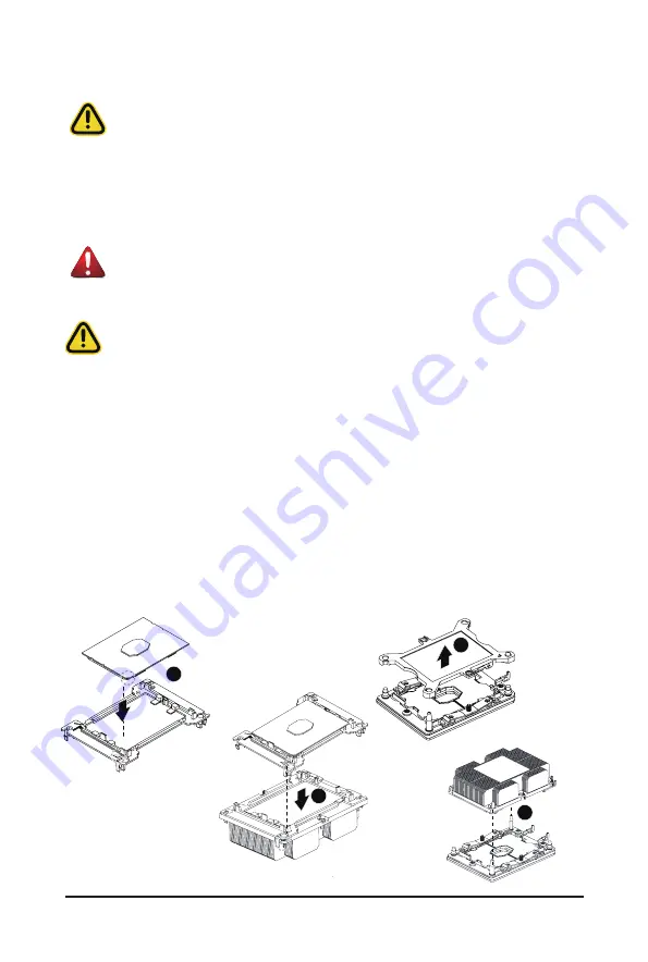
Follow these instructions to install the CPU:
1. Align the processor to the carrier so that the gold triangle on the processor aligns with the triangle
on the carrier, and then install the processor into the carrier.
NOTE:
Apply thermal compound evenly on the top of the CPU.
2.
Carefully flip the heatsink over. Align the carrier assembly so that the triangle on the carrier aligns
with the triangle on the heatsink, and then install the carrier assembly onto the bottom of the
heatsink.
3. Remove the CPU socket cover.
NOTE:
Save and replace the CPU socket cover if the processor is removed from its socket.
4. Align the heatsink to the CPU socket using the guide pins and make sure the gold triangle is in the
correct orientation. Then place the heatsink onto the top of the CPU socket.
5. Secure the heatsink by tightening the screws in sequential order (1
g
2
g
3
g
4).
NOTE:
When removing the heatsink, loosen the screws in reverse order (4
g
3
g
2
g
1).
1
2
3
4
Содержание G241-G40
Страница 1: ...G241 G40 HPC Server 2U 4 x GPU Server User Manual Rev 1 0 ...
Страница 10: ... 10 This page intentionally left blank ...
Страница 16: ...1 3 System Block Diagram ...
Страница 28: ...System Hardware Installation 28 1 2 3 4 ...
Страница 37: ... 37 System Hardware Installation 3 12 Cable Routing Front Panel LEDs and Buttons Front Panel USB 3 0 Port ...
Страница 38: ...System Hardware Installation 38 System Main Power MB Bo om Power Connector Onboard SATA SGPIO ...
Страница 39: ... 39 System Hardware Installation HDD Backplane Board Power HDD Backplane Board Fan Power ...
Страница 40: ...System Hardware Installation 40 PMBus Signal MB Bo om Power Connector GPU Riser Card Power ...
Страница 41: ... 41 System Hardware Installation GPU Power 300W GPU Signal 0 ...
Страница 42: ...System Hardware Installation 42 GPU Signal 1 GPU Signal 2 ...
Страница 43: ... 43 System Hardware Installation GPU Signal 3 U2_A1 U2_B1 ...
Страница 44: ...System Hardware Installation 44 This page intentionally left blank ...
Страница 48: ...Motherboard Components 48 This page intentionally left blank ...
Страница 69: ... 69 BIOS Setup 5 2 12 Intel R X722 Gigabit Network Connection ...
Страница 71: ...BIOS Setup 71 5 2 13 VLAN Configuration ...
Страница 75: ...BIOS Setup 75 5 3 1 Processor Configuration ...
Страница 78: ...BIOS Setup 78 5 3 3 UPI Configuration ...


