background image

CPU Speed Setup  

18 

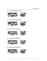
40. Cyrix / IBM 6x86MX-PR200 (75*2 2.9V) 


SW2 

ON 

6  5 4  3 2 1 

SW1 

ON 

3  4 


41. Cyrix / IBM 6x86MX-PR233 (66*3 2.9V) 


SW2 

ON 

6  5 4  3 2 1 

SW1 

ON 

3  4 


42. Cyrix / IBM 6x86MX-PR233 (75*2.5 2.9V) 


SW2 

ON 

6  5 4  3 2 1 

SW1 

ON 

3  4 


43. Cyrix / IBM 6x86MX-PR233 (83*2 2.9V) 


SW2 

ON 

6  5 4  3 2 1 

SW1 

ON 

3  4 


44. Cyrix / IBM 6x86MX-PR266 (66*3.5 2.9V) 


SW2 

ON 

6  5 4  3 2 1 

SW1 

ON 

3  4 


Содержание 5VMM

Страница 1: ...dio television technician for additional suggestions You are cautioned that any change or modifications to the equipment not expressly approve by the party responsible for compliance could void Your authority to operate such equipment This device complies with Part 15 of the FCC Rules Operation is subjected to the following two conditions 1 this device may not cause harmful interference and 2 this...

Страница 2: ... apparatus Residual commercial and light industry EN 55015 Limits and methods of measurement EN 55081 2 Generic emission standard Part 2 of radio disturbance characteristics of Industrial environment fluorescent lamps and luminaries EN 55020 Immunity from radio interference of EN 55082 2 Generic immunity standard Part 2 broadcast receivers and associated Industrial environment equipment EN 55022 L...

Страница 3: ...5VMM Socket 7 Processor Motherboard USER S MANUAL Socket 7 Processor Motherboard REV 2 1 First Edition R 21 01 000712 ...

Страница 4: ......

Страница 5: ...evision information 2 Item Checklist Product item list 3 Features Product information specification 4 Hardware Setup Instructions on setting up the motherboard 5 Performance Block Diagram Product performance block diagram 6 BIOS Setup Instructions on setting up the BIOS software 7 Appendix General reference ...

Страница 6: ......

Страница 7: ...cklist P 2 Summary of Features P 3 5VMM Motherboard Layout P 4 Page Index for CPU Speed Setup Connectors Panel and Jumper Definition P 5 Performance List P 37 Block Diagram P 38 Memory Installation P 39 Page Index for BIOS Setup P 40 Appendix P 73 ...

Страница 8: ...oard user s manual Jul 2000 The author assumes no responsibility for any errors or omissions that may appear in this document nor does the author make a commitment to update the information contained herein Third party brands and names are the property of their respective owners Jul 12 2000 Taipei Taiwan ...

Страница 9: ...tem Checklist þThe 5VMM motherboard þCable for IDE floppy device þDiskettes or CD TUCD for motherboard driver utility oInternal COM B Cable Optional oInternal USB Cable Optional oCable for SCSI device þ5VMM user s manual ...

Страница 10: ... 3 4 UDMA33 ATA66 IDE ATAPI CD ROM On Board Peripherals Ÿ 1 floppy port supports 2 FDD with 360K 720K 1 2M 1 44M and 2 88M bytes Ÿ 1 parallel ports supports SPP EPP ECP mode Ÿ 1 serial ports COM A Ÿ 4 USB ports Front USB is optional Ÿ 1 IrDA connector for IR Hardware Monitor Ÿ CPU System fan revolution detect Ÿ CPU System temperature detect Ÿ System voltage detect Ÿ CPU overheat shutdown detect On...

Страница 11: ... Motherboard Layout 4 5VMM Motherboard Layout PCI2 PCI3 VT82C686A io PS 2 SW2 ISA DIMM1 5VMM PCI1 BAT1 Socket 7 CPU USB VT8501 J1 J9 J6 AMR SW1 J12 J15 Front USB AC97 JP7 JP6 JP5 JP4 J5 J4 JP2 J3 JP3 J7 J2 ...

Страница 12: ...t P 28 IDE 1 Primary IDE 2 Secondary Port P 28 J15 CD Audio Line In P 29 J12 AUX_IN Optional P 29 J9 TEL Optional P 30 J5 Ring Power On Optional P 30 J4 Wake on LAN Optional P 31 J3 IR Connector P 31 Panel and Jumper Definition P 32 J7 2x11 Pins Jumper P 32 JP1 Clear CMOS Function P 33 JP5 JP6 JP7 Onboard AC97 AMR Select P 33 J6 USB Device Wake up Selection Optional P 34 JP4 Onboard LAN Function O...

Страница 13: ...O X O O 3 0V X O X O X 1 9V X X O O O 3 1V O O X O X 2 0V X O O O O 3 2V X X O O X 2 1V O X X X X 3 3V O X O O X 2 2V X O X X X 3 4V X O O O X 2 3V O O X X X 3 5V O O O O X 2 4V X X O X X CPU Ratio SW2 6 7 8 X1 5 X X X X2 O X X X2 5 O O X X3 X O X X3 5 X X X X4 O X O X4 5 O O O X5 X O O X5 5 X X O SW1 FSB S1 S2 S3 S4 66 O X X X 75 X X X O 83 O X O X 90 O O X X 95 X O O X 97 X X O X 100 O O O X Not...

Страница 14: ... X X X O X O O O X 14 AMD K6 2 333 66 5 2 2V X O X X X X O O O X X X 15 AMD K6 2 333 95 3 5 2 2V X O X X X X X X X O O X 16 AMD K6 2 350 100 3 5 2 2V X O X X X X X X O O O X 17 AMD K6 2 366 66 5 5 2 2V X O X X X X X O O X X X 18 AMD K6 2 380 95 4 2 2V X O X X X O X O X O O X 19 AMD K6 2 400 100 4 2 2V X O X X X O X O O O O X 20 AMD K6 2 450 100 4 5 2 2V X O X X X O O O O O O X 21 AMD K6 2 450 100 ...

Страница 15: ... O X O X X X 40 Cyrix IBM 6x86MX PR200 75 2 2 9V O X X O X O X X X X X O 41 Cyrix IBM 6x86MX PR233 66 3 2 9V O X X O X X O X O X X X 42 Cyrix IBM 6x86MX PR233 75 2 5 2 9V O X X O X O O X X X X O 43 Cyrix IBM 6x86MX PR233 83 2 2 9V O X X O X O X X O X O X 44 Cyrix IBM 6x86MX PR266 66 3 5 2 9V O X X O X X X X O X X X 45 Cyrix IBM 6x86MX PR266 75 3 2 9V O X X O X X O X X X X O 46 Cyrix IBM 6x86MX PR2...

Страница 16: ...inchip 2 233 66 3 5 3 5V O O O O X X X X O X X X 62 IDT Winchip 2 266 66 4 3 5V O O O O X O X O O X X X 63 IDT Winchip 2 266 100 2 33 3 5V O O O O X X O O O O O X 64 IDT Winchip 2 300 100 2 5 3 5V O O O O X O O X O O O X 65 IDT Winchip 3 266 100 2 33 2 8V X X X O X X O O O O O X 66 RISE MP6 266 100 2 2 8V X X X O X O X X O O O X Note If Cyrix 6x86 is being used please check the CPU Date Code after...

Страница 17: ...or 133 MHz SW2 ON 6 5 4 3 2 1 7 8 SW1 ON 3 4 2 1 2 Pentium Processor 166 MHz SW2 ON 6 5 4 3 2 1 7 8 SW1 ON 3 4 2 1 3 Pentium Processor 200 MHz SW2 ON 6 5 4 3 2 1 7 8 SW1 ON 3 4 2 1 4 Intel MMX 166 MHz SW2 ON 6 5 4 3 2 1 7 8 SW1 ON 3 4 2 1 ...

Страница 18: ...4 3 2 1 7 8 SW1 ON 3 4 2 1 6 Intel MMX 233 MHz SW2 ON 6 5 4 3 2 1 7 8 SW1 ON 3 4 2 1 7 AMD K6 166 2 9V SW2 ON 6 5 4 3 2 1 7 8 SW1 ON 3 4 2 1 8 AMD K6 200 2 9V SW2 ON 6 5 4 3 2 1 7 8 SW1 ON 3 4 2 1 9 AMD K6 233 3 2V SW2 ON 6 5 4 3 2 1 7 8 SW1 ON 3 4 2 1 ...

Страница 19: ...K6 266 66 4 2 2V AMD K6 2 266 66 4 2 2V SW2 ON 6 5 4 3 2 1 7 8 SW1 ON 3 4 2 1 12 AMD K6 300 66 4 5 2 2V SW2 ON 6 5 4 3 2 1 7 8 SW1 ON 3 4 2 1 13 AMD K6 300 100 3 2 2V AMD K6 2 300 100 3 2 2V SW2 ON 6 5 4 3 2 1 7 8 SW1 ON 3 4 2 1 14 AMD K6 2 333 66 5 2 2V SW2 ON 6 5 4 3 2 1 7 8 SW1 ON 3 4 2 1 ...

Страница 20: ...1 ON 3 4 2 1 16 AMD K6 2 350 100 3 5 2 2V SW2 ON 6 5 4 3 2 1 7 8 SW1 ON 3 4 2 1 17 AMD K6 2 366 66 5 5 2 2V SW2 ON 6 5 4 3 2 1 7 8 SW1 ON 3 4 2 1 18 AMD K6 2 380 95 4 2 2V SW2 ON 6 5 4 3 2 1 7 8 SW1 ON 3 4 2 1 19 AMD K6 2 400 100 4 2 2V SW2 ON 6 5 4 3 2 1 7 8 SW1 ON 3 4 2 1 ...

Страница 21: ...W1 ON 3 4 2 1 21 AMD K6 2 450 100 4 5 2 4V SW2 ON 6 5 4 3 2 1 7 8 SW1 ON 3 4 2 1 22 AMD K6 2 475 95 5 2 2V SW2 ON 6 5 4 3 2 1 7 8 SW1 ON 3 4 2 1 23 AMD K6 2 475 95 5 2 4V SW2 ON 6 5 4 3 2 1 7 8 SW1 ON 3 4 2 1 24 AMD K6 2 500 100 5 2 2V SW2 ON 6 5 4 3 2 1 7 8 SW1 ON 3 4 2 1 ...

Страница 22: ...ON 3 4 2 1 26 AMD K6 2 500 100 5 2 4V SW2 ON 6 5 4 3 2 1 7 8 SW1 ON 3 4 2 1 27 AMD K6 2 533 97 5 5 2 2V SW2 ON 6 5 4 3 2 1 7 8 SW1 ON 3 4 2 1 28 AMD K6 2 550 100 5 5 2 2V SW2 ON 6 5 4 3 2 1 7 8 SW1 ON 3 4 2 1 29 AMD K6 III 400 100 4 2 2V SW2 ON 6 5 4 3 2 1 7 8 SW1 ON 3 4 2 1 ...

Страница 23: ... 3 4 2 1 31 AMD K6 III 450 100 4 5 2 2V SW2 ON 6 5 4 3 2 1 7 8 SW1 ON 3 4 2 1 32 AMD K6 III 450 100 4 5 2 4V SW2 ON 6 5 4 3 2 1 7 8 SW1 ON 3 4 2 1 33 AMD K6 III 475 95 5 2 2V SW2 ON 6 5 4 3 2 1 7 8 SW1 ON 3 4 2 1 34 AMD K6 III 475 95 5 2 4V SW2 ON 6 5 4 3 2 1 7 8 SW1 ON 3 4 2 1 ...

Страница 24: ...1 36 AMD K6 III 500 100 5 2 4V SW2 ON 6 5 4 3 2 1 7 8 SW1 ON 3 4 2 1 37 AMD K6 III 550 100 5 5 2 2V SW2 ON 6 5 4 3 2 1 7 8 SW1 ON 3 4 2 1 38 Cyrix IBM 6x86MX PR166 66 2 2 9V SW2 ON 6 5 4 3 2 1 7 8 SW1 ON 3 4 2 1 39 Cyrix IBM 6x86MX PR200 66 2 5 2 9V SW2 ON 6 5 4 3 2 1 7 8 SW1 ON 3 4 2 1 ...

Страница 25: ... Cyrix IBM 6x86MX PR233 66 3 2 9V SW2 ON 6 5 4 3 2 1 7 8 SW1 ON 3 4 2 1 42 Cyrix IBM 6x86MX PR233 75 2 5 2 9V SW2 ON 6 5 4 3 2 1 7 8 SW1 ON 3 4 2 1 43 Cyrix IBM 6x86MX PR233 83 2 2 9V SW2 ON 6 5 4 3 2 1 7 8 SW1 ON 3 4 2 1 44 Cyrix IBM 6x86MX PR266 66 3 5 2 9V SW2 ON 6 5 4 3 2 1 7 8 SW1 ON 3 4 2 1 ...

Страница 26: ... 3 4 2 1 46 Cyrix IBM 6x86MX PR266 83 2 5 2 9V SW2 ON 6 5 4 3 2 1 7 8 SW1 ON 3 4 2 1 47 Cyrix M º PR300 66 3 5 2 9V SW2 ON 6 5 4 3 2 1 7 8 SW1 ON 3 4 2 1 48 Cyrix M º PR333 66 4 2 9V SW2 ON 6 5 4 3 2 1 7 8 SW1 ON 3 4 2 1 49 Cyrix M º PR333 83 3 2 9V SW2 ON 6 5 4 3 2 1 7 8 SW1 ON 3 4 2 1 ...

Страница 27: ... 3 4 2 1 51 Cyrix M º PR333 100 2 5 2 9V SW2 ON 6 5 4 3 2 1 7 8 SW1 ON 3 4 2 1 52 Cyrix M º PR350 90 3 2 9V SW2 ON 6 5 4 3 2 1 7 8 SW1 ON 3 4 2 1 53 Cyrix M º PR366 75 4 2 9V SW2 ON 6 5 4 3 2 1 7 8 SW1 ON 3 4 2 1 54 Cyrix M º PR366 83 3 5 2 9V SW2 ON 6 5 4 3 2 1 7 8 SW1 ON 3 4 2 1 ...

Страница 28: ... 4 2 1 56 Cyrix M º PR400 90 4 2 9V SW2 ON 6 5 4 3 2 1 7 8 SW1 ON 3 4 2 1 57 Cyrix M º PR400 100 3 5 2 9V SW2 ON 6 5 4 3 2 1 7 8 SW1 ON 3 4 2 1 58 IDT Winchip 2 200 66 3 3 5V SW2 ON 6 5 4 3 2 1 7 8 SW1 ON 3 4 2 1 59 IDT Winchip 2 200 100 2 3 5V SW2 ON 6 5 4 3 2 1 7 8 SW1 ON 3 4 2 1 ...

Страница 29: ... 1 61 IDT Winchip 2 233 66 3 5 3 5V SW2 ON 6 5 4 3 2 1 7 8 SW1 ON 3 4 2 1 62 IDT Winchip 2 266 66 4 3 5V SW2 ON 6 5 4 3 2 1 7 8 SW1 ON 3 4 2 1 63 IDT Winchip 2 266 100 2 33 3 5V SW2 ON 6 5 4 3 2 1 7 8 SW1 ON 3 4 2 1 64 IDT Winchip 2 300 100 2 5 3 5V SW2 ON 6 5 4 3 2 1 7 8 SW1 ON 3 4 2 1 ...

Страница 30: ...5VMM Motherboard 23 65 IDT Winchip 3 266 100 2 33 2 8V SW2 ON 6 5 4 3 2 1 7 8 SW1 ON 3 4 2 1 66 RISE MP6 266 100 2 2 8V SW2 ON 6 5 4 3 2 1 7 8 SW1 ON 3 4 2 1 ...

Страница 31: ...Connectors 24 Connectors Game Audio Port MIC In Game Port Line In Line Out COM A VGA LPT Port COM A LPT Port VGA ...

Страница 32: ...0 2 USB D0 3 USB D0 4 GND 5 USB V1 6 USB D1 7 USB D1 8 GND 2 1 1 Green LED LAN Link LED 2 Yellow LED LAN Active LED 5 6 7 8 1 2 3 4 PS 2 Keyboard PS 2 Mouse Connector PS 2 Mouse Keyboard Pin No Definition 1 Data 2 NC 3 GND 4 VCC 5V 5 Clock 6 NC PS 2 Keyboard PS 2 Mouse 1 2 3 4 5 6 ...

Страница 33: ...Connectors 26 J1 CPU Fan Pin No Definition 1 GND 2 12V 3 SENSE 1 J2 System Fan Pin No Definition 1 GND 2 12V 3 SENSE 1 ...

Страница 34: ...3 5 7 13 15 17 GND 1 2 11 3 3V 4 6 19 20 VCC 10 12V 12 12V 18 5V 8 Power Good 9 5V SB stand by 5V 14 PS ON Soft On Off 10 11 20 1 Front USB Optional Pin No Definition 1 5V SB 2 GND 3 USB D2 4 NC 5 USB D2 6 USB D3 7 NC 8 USB D3 9 GND 10 5V SB 1 10 9 2 ...

Страница 35: ...Connectors 28 Floppy Port Red Line IDE1 Primary IDE2 Secondary Port IDE 1 IDE 2 Red Line ...

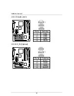
Страница 36: ...5VMM Motherboard 29 J15 CD Audio Line In Pin No Definition 1 CD L 2 GND 3 GND 4 CD R 1 J12 AUX_IN Optional 1 Pin No Definition 1 AUX L 2 GND 3 GND 4 AUX R ...

Страница 37: ...9 TEL The connector is for Modem with internal voice connector Optional 1 Pin No Definition 1 Signal In 2 GND 3 GND 4 Signal Out J5 Ring Power On Internal Modem Card Wake Up Optional Pin No Definition 1 Signal 2 GND 1 ...

Страница 38: ...5VMM Motherboard 31 J4 Wake On LAN Optional Pin No Definition 1 5V SB 2 GND 3 Signal 1 J3 IR Connector PIN No Definition 1 VCC 5V 2 NC 3 IR data input 4 GND 5 IR data output 1 ...

Страница 39: ...reen Mode GD Green LED Pin 1 LED anode Pin 2 LED cathode HD IDE Hard Disk Active LED Pin 1 LED anode Pin 2 LED cathode SPK Speaker Connector Pin 1 VCC Pin 2 Pin 3 NC Pin 4 Data RE Reset Switch Open Normal Operation Close Reset Hardware System P P P Power LED Pin 1 LED anode Pin 2 LED cathode Pin 3 LED cathode PW Soft Power Connector Open Normal Operation Close Power On Off ...

Страница 40: ...efault 2 3 close Clear CMOS JP5 JP6 JP7 Onboard AC97 AMR Primary or Secondary Select AMRà Audio Modem Riser Jumper Function JP5 JP6 JP7 Only AC97 1 2 Close 1 2 Close OFF Only AMR Primary 3 4 Close 3 4 Close OFF AC97 MR Secondary Default 1 2 Close 3 4 Close 1 2 Close ON 1 JP6 JP5 JP7 ...

Страница 41: ... Device Wake up Selection Optional Pin No Definition 1 2 close Normal Default 2 3 close Enabled USB Device Wake up 1 JP4 Onboard LAN Function Optional Pin No Definition 1 2 close Onboard LAN Enabled Default 2 3 close Onboard LAN Disabled 1 ...

Страница 42: ...ition Close BIOS Write Protection Open Normal Default MPlease set Jumper JP2 to Open to enabled BIOS write function when you update new BIOS or new device JP3 Internal Buzzer Connector Optional Pin No Definition Open Internal Buzzer Disabled Close Internal Buzzer Enabled Default 1 ...

Страница 43: ...tion 36 BAT1 Battery Danger of explosion if battery is incorrectly replaced Replace only with the same or equivalent type recommended by the manufacturer Dispose of used batteries according to the manufacturer s instructions ...

Страница 44: ...sor DRAM 128x1 MB SDRAM CACHE SIZE 512 KB included in CPU DISPLAY Onboard AGP VIA Trident Bland 3D MVP4 8MB SDRAM STORAGE Onboard IDE Quantum KA13600AT O S Windows NTTM 4 0 SPK6 DRIVER Display Driver at 1024 x 768 x 16bit colors x 75Hz AMD Processor K6 III 450MHz 100x4 5 K6 2 500MHz 100x5 K6 2 450MHz 100x4 5 Winbench99 CPU mark99 39 6 12 1 28 8 FPU Winmark 99 1520 1570 1520 Business Disk Winmark 9...

Страница 45: ...318MHz 33 MHz PCI Bus LPT Port PS 2 KB Mouse COM Port IR USB Bus 14 318MHz 48MHz Host Bus VIA VT8501 VIA VT82C686A 66 100 MHz 66 100 MHz 33 MHz ISA Bus AC97 CODEC Ultra DMA 33 ATA66 IDE Ports AMR Slot AC 97 Link IDE Bus USB Port 66 100 MHz 24MHz ICS 9248 127 Socket 7 CPU ...

Страница 46: ... and size To install the memory module just push it vertically into the DIMM Slot The DIMM module can only fit in one direction due to the two notch Memory size can vary between sockets Install memory in any combination table DIMM 168 pin SDRAM DIMM Modules DIMM1 Supports 16 32 64 128 256 512MB X 1 pcs DIMM2 Supports 16 32 64 128 256 512MB X 1 pcs ...

Страница 47: ...BIOS Features P 49 Advanced Chipset Features P 53 Integrated Peripherals P 56 Power Management Setup P 61 PnP PCI Configurations P 65 Frequency Voltage Control P 67 Load Fail Safe Defaults P 68 Load Optimized Defaults P 69 Set Supervisor User Password P 70 Save Exit Setup P 71 Exit Without Saving P 72 ...

Страница 48: ...rt by simultaneously press Ctrl Alt Del keys CONTROL KEYS Move to previous item Move to next item Move to the item in the left hand Move to the item in the right hand Esc Main Menu Quit and not save changes into CMOS Status Page Setup Menu and Option Page Setup Menu Exit current page and return to Main Menu PgUp Increase the numeric value or make changes PgDn Decrease the numeric value or make cha...

Страница 49: ...ll appear on the screen The Main Menu allows you to select from nine setup functions and two exit choices Use arrow keys to select among the items and press Enter to accept or enter the sub menu Figure 1 Main Menu CMOS Setup Utility Copyright C 1984 2000 Award Software 4Standard CMOS Features Load Fail Safe Defaults 4Advanced BIOS Features Load Optimized Defaults 4Advanced Chipset Features Set Sup...

Страница 50: ...nfigurations This setup page includes all the configurations of PCI PnP ISA resources Frequency Voltage Control This setup page is control CPU s clock and frequency ratio Load Fail Safe Defaults Fail Safe Defaults indicates the value of the system parameters which the system would be in safe configuration Load Optimized Defaults Optimized Defaults indicates the value of the system parameters which...

Страница 51: ...BIOS Setup 44 Save Exit Setup Save CMOS value settings to CMOS and exit setup Exit Without Saving Abandon all CMOS value changes and exit setup ...

Страница 52: ...or the maximum allowed in the month Year The year from 1994 through 2079 CMOS Setup Utility Copyright C 1984 2000 Award Software Standard CMOS Features Date mm dd yy Fri Jan 7 2000 Item Help Time hh mm ss 2 31 24 Menu Level 4 4IDE Primary Master Press Enter None 4IDE Primary Slave Press Enter None Change the 4IDE Secondary Master Press Enter None Day month 4IDE Secondary Slave Press Enter None Yea...

Страница 53: ...following items Enter the information directly from the keyboard and press Enter Such information should be provided in the documentation form your hard disk vendor or the system manufacturer CYLS Number of cylinders HEADS number of heads PRECOMP write precomp LANDZONE Landing zone SECTORS number of sectors If a hard disk has not been installed select NONE and press Enter Drive A Drive B The categ...

Страница 54: ...s Adapter power up in 40 column mode CGA 80 Color Graphics Adapter power up in 80 column mode MONO Monochrome adapter includes high resolution monochrome adapters Halt on The category determines whether the computer will stop if an error is detected during power up NO Errors The system boot will not stop for any error that may be detected and you will be prompted All Errors Whenever the BIOS detec...

Страница 55: ...ional memory installed in the system The value of the base memory is typically 512 K for systems with 512 K memory installed on the motherboard or 640 K for systems with 640 K or more memory installed on the motherboard Extended Memory The BIOS determines how much extended memory is present during the POST This is the amount of memory located above 1 MB in the CPU s memory address map ...

Страница 56: ...dvanced BIOS Features Virus Warning Disabled Item Help CPU Internal Cache Enabled Quick Power On Self Test Enabled Menu Level 4 First Boot Device Floppy Allows you to Second Boot Device HDD 0 choose the VIRUS Third Boot Device LS120 Warning feature Boot Other Device Enabled For IDE Hard disk Swap Floppy Drive Disabled Boot sector Boot Up Floppy Seek Enabled Protection If this Boot Up NumLock Statu...

Страница 57: ...nd Third Boot device Floppy Select your boot device priority by Floppy LS120 Select your boot device priority by LS120 HDD 0 3 Select your boot device priority by HDD 0 3 SCSI Select your boot device priority by SCSI CDROM Select your boot device priority by CDROM ZIP100 Select your boot device priority by ZIP100 Disabled Disabled this function LAN Select your boot device priority by LAN Boot othe...

Страница 58: ...Option Normal Set Gate A20 Option is Normal Fast Set Gate A20 Option is Fast Default value Typematic Rate Setting Enabled Enable Keyboard Typematic rate setting Disabled Disable Keyboard Typematic rate setting Default value Typematic Rate Chars Sec 6 30 Set the maximum Typematic rate from 6 chars Per second to 30 characters Per second Default value 6 Typematic Delay Msec 250 1000 Set the time dela...

Страница 59: ...ult value Report No FDD For WIN 95 No Assign IRQ6 For FDD Yes FDD Detect IRQ6 Automatically Default value Video BIOS Shadow It determines whether video BIOS is able to copy to RAM however it is optional from chipset design Video Shadow will increase the video speed Enabled Video shadow is enabled Default value Disabled Video shadow is disabled Cyrix 6x86 M II CPUID Enabled Enabled Cyrix 6x86 M II ...

Страница 60: ...led DRAM Read Pipeline Disabled Disabled DRAM Read Pipeline Default value CMOS Setup Utility Copyright C 1984 2000 Award Software Advanced Chipset Features Bank 0 1 DRAM Timing SDRAM 10ns Item Help Bank 2 3 DRAM Timing SDRAM 10ns SDRAM Cycle Length 3 Menu Level 4 DRAM Read Pipeline Disabled Video BIOS Cacheable Enabled System BIOS Cacheable Enabled Memory Hole Disabled Init Display First PCI Slot ...

Страница 61: ...lue AGP System will boot from AGP Display Card first Frame Buffer Size 4MB Set Frame Buffer Size to 4MB 8MB Set Frame Buffer Size to 8 MB Default Value NA Disabled this function AGP Aperture Size 4MB Set AGP Aperture Size to 4MB 8MB Set AGP Aperture Size to 8MB 16MB Set AGP Aperture Size to 16MB 32MB Set AGP Aperture Size to 32MB 64MB Set AGP Aperture Size to 64MB Default Value 128MB Set AGP Apert...

Страница 62: ...ult Value Disabled Disabled this function OnChip Modem Enabled Enabled OnChip Modem Default Value Disabled Disabled this function Memory Parity ECC Check Enabled Enabled Memory Parity ECC Check Function Disabled Disabled Memory Parity ECC Check Function Default Value ...

Страница 63: ...Secondary Slave PIO Auto Primary Master UDMA Auto Primary Slave UDMA Auto Secondary Master UDMA Auto Secondary Slave UDMA Auto IDE HDD Block Mode Enabled Onboard FDD Controller Enabled Onboard Serial Port 1 Auto Onboard Serial Port 2 Auto UART 2 Mode HPSIR IR Function Duplex Half TX RX inverting enable No Yes Onboard Parallel Port 378 IRQ7 Onboard Parallel Mode Normal ä ECP Mode Use DMA 3 ä Parall...

Страница 64: ...lly detect the IDE HDD Accessing mode Default value Mode0 4 Manually set the IDE Accessing mode Secondary Master PIO for onboard IDE 2nd channel Auto BIOS will automatically detect the IDE HDD Accessing mode Default value Mode0 4 Manually set the IDE Accessing mode Secondary Slave PIO for onboard IDE 2nd channel Auto BIOS will automatically detect the IDE HDD Accessing mode Default value Mode0 4 M...

Страница 65: ... Port 1 Auto BIOS will automatically setup the port 1 address Default value 3F8 IRQ4 Enable onboard Serial port 1 and address is 3F8 2F8 IRQ3 Enable onboard Serial port 1 and address is 2F8 3E8 IRQ4 Enable onboard Serial port 1 and address is 3E8 2E8 IRQ3 Enable onboard Serial port 1 and address is 2E8 Disabled Disable onboard Serial port 1 Onboard Serial Port 2 Auto BIOS will automatically setup ...

Страница 66: ... Yes Yes Set TX RX Inverting enabled to Yes Yes Onboard Parallel port 378 IRQ7 Enabled onboard LPT port and address is 378 IRQ7 Default value 278 IRQ5 Enabled onboard LPT port and address is 278 IRQ5 Disabled Disabled onboard LPT port 3BC IRQ7 Enabled onboard LPT port and address is 3BC IRQ7 Onboard Parallel Mode Normal Normal Setting Default value EPP Using Parallel port as Enhanced Parallel Port...

Страница 67: ... I O Base Address is 260h 280H Set SB I O Base Address is 280h SB IRQ Select IRQ 5 9 10 Default Value 5 SB DMA Select DMA 0 1 2 3 Default Value 1 MPU 401 Enabled Enabled MPU 401 Disabled Disabled MPU 401 Default Value MUP 401 I O Address 330 333H Set MUP 401 I O Address is 330 333H Default Value 300 303H Set MUP 401 I O Address is 300 303H 310 313H Set MUP 401 I O Address is 310 313H 320 323H Set ...

Страница 68: ...e 10Sec 1 Hour Setup the timer to enter Doze Mode Suspend Mode Disabled Disabled Suspend Mode 10Sec 1 Hour Setup the timer to enter Suspend Mode CMOS Setup Utility Copyright C 1984 2000 Award Software Power Management Setup Power Management Press Enter Item Help PM Control by APM Yes Video Off Option SuspendgOff Menu Level 4 Video Off Method DPMS Support MODEM Use IRQ 4 Soft Off by PWRBTN Instant ...

Страница 69: ...ack monitor when gets into Green mode DPMS Support BIOS will use DPMS Standard to control VGA card The Green type VGA card will turn off V H SYNC automatically Default value MODEM Use IRQ NA Set MODEM Use IRQ to NA 3 Set MODEM Use IRQ to 3 4 Set MODEM Use IRQ to 4 Default value 5 Set MODEM Use IRQ to 5 7 Set MODEM Use IRQ to 7 9 Set MODEM Use IRQ to 9 10 Set MODEM Use IRQ to 10 11 Set MODEM Use IR...

Страница 70: ...lue NONE Normal Operation LPT Enabled LPT Ports Activity COM Enabled COM Ports Activity HDD FDD ON Enabled HDD FDD Ports Activity Default value OFF Disabled HDD FDD Ports Activity DMA master ON Don t detect DMA master PM event OFF Normal Operation Default value PowerOn by PCI Card Disabled Disabled this function Enabled Enabled PowerOn by PCI Card Default value Wake Up On LAN Ring Disabled Disable...

Страница 71: ... Enabled alarm function to POWER ON system If the RTC Alarm Resume is Enabled Date of Month Alarm 0 31 Resume Time hh mm ss Alarm 0 23 0 59 0 59 Primary INTR OFF Disabled this function ON Enabled Primary INTR Function Default value IRQ 3 15 Disabled Disabled this function Primary The resource is used by Primary device Secondary The resource is used by Secondary device ...

Страница 72: ... CMOS Setup Utility Copyright C 1984 2000 Award Software PnP PCI Configurations PNP OS Installed No Item Help Reset Configuration Data Disabled Menu Level 4 Resources Controlled By Auto ESCD X IRQ Resources Press Enter When resources are X DMA Resources Press Enter controlled manually assign each system interrupt a type PCI VGA Palette Snoop Disabled depending on the type Assign IRQ For VGA Enable...

Страница 73: ...gacyISA The resource is used by Legacy ISA device PCI ISAPnP The resource is used by PCI ISA PnP device PCI or ISA PCI VGA Palette Snoop Enabled ForhavingVideoCardonISABusandVGACardonPCIBus Disabled For VGA Card only Default value Assign IRQ For VGA Enabled Assign a specific IRQ for VGA Default value Disabled No IRQ is assigned for VGA Assign IRQ For USB Enabled Assign a specific IRQ for USB Defau...

Страница 74: ... Modulated Disabled Disabled this function Default value 0 25 Set Spread Spectrum to 0 25 0 5 Set Spread Spectrum to 0 5 CMOS Setup Utility Copyright C 1984 2000 Award Software Frequency Voltage Control Auto Detect DIMM PCI Clk Enabled Item Help Spread Spectrum Modulated Disabled Menu Level 4 Move Enter Select PU PD Value F10 Save ESC Exit F1 General Help F5 Previous Values F6 Fail Safe Defaults F...

Страница 75: ... Copyright C 1984 2000 Award Software 4Standard CMOS Features Load Fail Safe Defaults 4Advanced BIOS Features Load Optimized Defaults 4Advanced Chipset Features Set Supervisor Password 4Integrated Peripherals Set User Password 4Power Management Setup Save Exit Setup 4PnP PCI Configurations Exit Without Saving 4Frequency Voltage Control ESC Quit Select Item F10 Save Exit Setup Load Fail Safe Defaul...

Страница 76: ...ity Copyright C 1984 2000 Award Software 4Standard CMOS Features Load Fail Safe Defaults 4Advanced BIOS Features Load Optimized Defaults 4Advanced Chipset Features Set Supervisor Password 4Integrated Peripherals Set User Password 4Power Management Setup Save Exit Setup 4PnP PCI Configurations Exit Without Saving 4Frequency Voltage Control ESC Quit Select Item F10 Save Exit Setup Load Optimized Def...

Страница 77: ...eing disabled Once the password is disabled the system will boot and you can enter Setup freely If you select System at Security Option in BIOS Features Setup Menu you will be prompted for the password every time the system is rebooted or any time you try to enter Setup Menu If you select Setup at Security Option in BIOS Features Setup Menu you will be prompted only when you try to enter Setup CMO...

Страница 78: ...84 2000 Award Software 4Standard CMOS Features Load Fail Safe Defaults 4Advanced BIOS Features Load Optimized Defaults 4Advanced Chipset Features Set Supervisor Password 4Integrated Peripherals Set User Password 4Power Management Setup Save Exit Setup 4PnP PCI Configurations Exit Without Saving 4Frequency Voltage Control ESC Quit Select Item F10 Save Exit Setup Save Data to CMOS SAVE to CMOS and E...

Страница 79: ...00 Award Software 4Standard CMOS Features Load Fail Safe Defaults 4Advanced BIOS Features Load Optimized Defaults 4Advanced Chipset Features Set Supervisor Password 4Integrated Peripherals Set User Password 4Power Management Setup Save Exit Setup 4PnP PCI Configurations Exit Without Saving 4Frequency Voltage Control ESC Quit Select Item F10 Save Exit Setup Abandon all Datas Quit Without Saving Y N...

Страница 80: ... Utility Insert the support CD that came with your motherboard into your CD ROM driver or double click the CD driver icon in My Computer to bring up the screen 1 2 3 4 5 6 1 Click VIA 4in 1 Service Pack Utility item 3 Click Yes 4 Click Next 5 Click Next 6 Click Next 2 Click Next Chipset ...

Страница 81: ...Appendix 74 7 8 9 10 7 Click Next 8 Click Next 10 Click Finish to restart 9 Click Next ...

Страница 82: ...otherboard into your CD ROM driver or double click the CD driver icon in My Computer to bring up the screen 1 2 3 4 5 6 2 Click Next 3 Click Next 5 Click Next 4 You can select Specify a location D VIA VGA Trident 8400 Win9x then Click Next 1 Click Change item 6 Click Next item ...

Страница 83: ...Appendix 76 7 7 Click Finish to restart computer ...

Страница 84: ...dio Driver Insert the support CD that came with your motherboard into your CD ROM driver or double click the CD driver icon in My Computer to bring up the screen 1 2 3 4 1 Click AC 97 Audio Driver item 3 Click Next 4 Click Finish to restart 2 Click Next Audio ...

Страница 85: ...lash utilities and BIOS file in j ü Restart your computer into MS DOS mode or command prompt only for Win95 98 go into the directory where the new BIOS file are located use the utility AWDFlash exe or AMIFlash exe to update the BIOS ü Type the following command once you have enter the directory where all the files are located C utility AWDFlash or AMIFlash filename of the BIOS binary file intended...

Страница 86: ...ock Addressing EMC Electromagnetic Compatibility BIOS Basic Input Output System SMI System Management Interrupt IRQ Interrupt Request NIC Network Interface Card A G P Accelerated Graphics Port S E C C Single Edge Contact Cartridge LED Light Emitting Diode EPP Enhanced Parallel Port CMOS Complementary Metal Oxide Semiconductor I O Input Output ESD Electrostatic Discharge OEM Original Equipment Manu...

Страница 87: ...endix 80 Acor Meaning PCI Peripheral Component Interconnect RIMM Rambus in line Memory Module DRM Dual Retention Mechanism ISA Industry Standard Architecture MTH Memory Translator Hub CRIMM Continuity RIMM ...

Отзывы: