


Inputs and Outputs
2500A Series Operation Manual, 34172 Revision C, March 2008
1.3.1
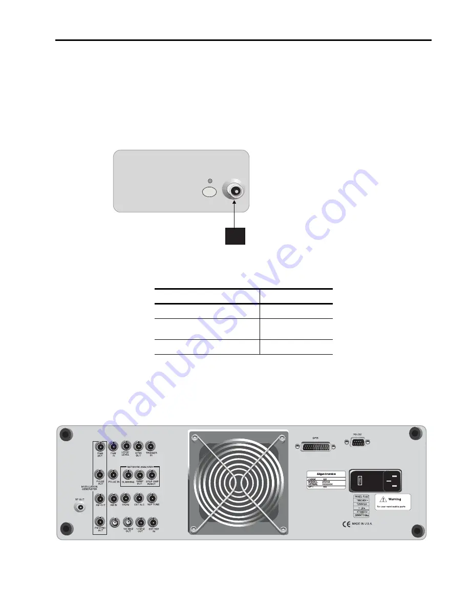
Front Panel Connector (RF Output)
This is the instrument’s RF output. It is located on the front panel of 2500B Series Synthesizer models,
and on the rear panel of versions of 2500S Series models.
The type of RF connector that is supplied depends on the frequency range of the instrument. Figure 1-2
shows the general location of the front panel RF output connector on 2500B Series models, and
Table 1-2 indicates by model the type of RF connector that is supplied.
Figure 1-2: Series 2500B Front Panel Output
1.3.2
Rear Panel Interface and I/O Connectors
This section defines the functions of the 2500A Series rear panel connectors (see Figure 1-3).
Table 1-2: RF Connector Types
Models
RF Connector Type
2508A/2508AS
N (f)
2520A/2520AS
2526A/2526AS
SMA (f)
2540A/2540AS
K (f)
ALC IN
RF OUT
RF
ON
Содержание 2508A
Страница 1: ...2500A Series 2500A Series Microwave Synthesizer Operations Manual 34172 Revision C March 2008 ...
Страница 4: ......
Страница 22: ...Chapter 1 2500A Introduction 22 2500A Series Operation Manual 34172 Revision C March 2008 ...
Страница 88: ...2500A Chapter 3 Remote Operation 88 2500A Series Operation Manual 34172 Revision C March 2008 ...
Страница 122: ...Chapter 4 Specifications Performance Verification 122 2500A Series Operation Manual 34172 Revision C March 2008 ...
Страница 132: ...2500A Series Microwave Synthesizer Error Messages 132 2500A Series Operation Manual 34172 Revision C March 2008 ...


