background image

Information

Technical And Operational Description

Card Data Format

Connections

Demo Software

Contents

....................................................................................................

4

6

12

14

15

...............................................

  ......................................................................................

....................................................................................................

............................................................................................

FCC COMPLIANCE STATEMENT

This equipment has been tested and found to comply with the limits for a Class A digital device,
pursuant to Part 15 of the FCC Rules. These limits are designed to provide reasonable protection
against harmful interference when the equipment is operated in a commercial environment. This
equipment generates, uses, and can radiate radio frequency energy and, if not installed and used in
accordance with the instruction manual, may cause harmful interference to radio communication.
Operation of this equipment in a residential area is likely to cause harmful interference in which
case the user will be required to correct the interference at his own expense.

21

................................................................................................

Specifications

22

.....................................................................

Communication Protocol

USB Driver Setup

.....................................................................

29

3

Содержание MSR120 Series

Страница 1: ... Preliminary October 2004 REGISTERED TO ISO 9001 2000 8F No 31 Lane 169 Kang Ning St Hsi Chih Taipei Hsien 221 Taiwan Phone 886 2 2695 4214 FAX 886 2 2695 4213 www gigatms com tw ...

Страница 2: ... is subject to change without notice No part of this document may be reproduced or transmitted in any form or by any means electronic or mechanical for any purpose without the express written permission of GIGA TMS Inc Rev Number Date Notes REVISIONS 01 8 Oct 04 Initial Release 2 ...

Страница 3: ...ion against harmful interference when the equipment is operated in a commercial environment This equipment generates uses and can radiate radio frequency energy and if not installed and used in accordance with the instruction manual may cause harmful interference to radio communication Operation of this equipment in a residential area is likely to cause harmful interference in which case the user ...

Страница 4: ...sed for a long time 5 Keep battery contact surfaces and battery compartment contacts clean by rubbing them with a clean pencil eraser or a rough cloth each time you replace batteries 6 Keep batteries away from children If swallowed contact a physician at once 7 Don t recharge a battery unless it is specifically marked rechargeable Attempts to recharge an alkaline battery may cause an imbalance wit...

Страница 5: ...Standard Package Main unit MSR120 RS232 Cable WAS T0017 LR03 AAA ALKALINE 1 5V Battery BAT T0010 Chain Sling TM09F1001 USB Cable for MSR120U series WAS 1571 CD ROM DISK5216 RS232 Cable for MSR120 series WAS T0017 5 ...

Страница 6: ...e card misread bad memory or incorrectly encoded data and so on the device will turn on the ERROR indicator Swipe Card Slot Swipe the card through the entire length of the slot to read Technical And Operational Description Battery Box Put the battery in box and hold battery Connector For connection to host computer and external Power Operate Keypad Turn the MSR120 on off power and Operate Operatio...

Страница 7: ... Decoded Track 3 be Decoded 000003 2 2 1 Current Record Number of Display or Store Main Menu Item Sub Menu Item 1 Corresponding Key Power Exit Back Cancel No Key Function 2 Corresponding Key 3 Corresponding Key 4 Corresponding Key Up Up scroll Increase Key Function Down Down scroll Decrease Key Function Menu Enter Save Next Yes Key Function Technical And Operational Description LCD Display Display...

Страница 8: ...ound ON OFF Reset Default BackLight 15 second Auto Power Off 30 second Power Mode Switch Mode Sound ON 3 1 Status 3 2 View Display Memory Status Used Space Unused Space Total Space Display all records in memory 4 1 Date Format 4 2 Set Date Time Set Date Format Select Year Month Date Date Month Year Month Date Year Set Date Year Month Date Set Time Week Hour Minute Second 5 1 Product Name Product D...

Страница 9: ...ready is full After swipe card LCD Display message Check RTC Check FLASH Decode Error No Record Recode not empty ISP MODE FLASH Full Counterplot Setting Date and Time Connect Agent Swipe Card again or Change Card Swipe Card Download Record and Erase Record Update New Firmware Download Record and Erase Record Status Power On Ready Read OK Read Error Green LED Take turns blink 2 times Off Blink 1 ti...

Страница 10: ...you must do the RTC time setting before you use the unit When powered by battery it would have Low Battery Detect function When the battery goes low the LCD would display and you must charge battery immediately otherwise the unit would shut down any time without pre warning 5 Swipe Card 6 Operate for Calendar 7 Memory Full Warning Log database memory is full You not be able to add any new records ...

Страница 11: ...ake the cover away 3 Take the battery away 4 Take new battery 5 Put new battery in 6 Fix the battery cover Note 1 Read the instructions on your device before replace new battery 2 MSR120 can used Single cell alkaline nickel cadmium NiCd or nickel metal hydride NiMH Battery 11 ...

Страница 12: ...nal power MSR120 DSUB 9P POWER JACK No use Note 1 When MSR120 is connected disconnected with external power adapter it would be turned On Off automatically 2 When MSR120 is not connected with external power adaptor the corresponding key for power on MSR120 needs to be pressed all the time during the communications with the PC 12 ...

Страница 13: ...ct to PC WAS 1571 1 1 Connections Note 1 When MSR120 is connected disconnected with USB port it would be turned On Off automatically USB 4P FEMALE PIN 1 3 2 4 FUNCTION VCC D D GND MINI USB 4P 1 3 2 4 FUNCTION RXD TXD VCC GND MSR120 13 ...

Страница 14: ... TRACK 3 1 03h is the physical track 3 2 SS is the start sentinel 3 ES is the end sentinel 4 Card Id up to 104 numeric data characters CARD ID Bits Per Inch 210 Bits Per Character 5 Track 3 Thrift Numeric Characters 107 DATE TIME WEEK M4 DATE DATE TIME WEEK SP TIME WEEK SP 1 FEh is the Separate Character 2 Date have 3 formats YYYY MM DD MM DD YYYY DD MM YYYY 3 SP is the SPACE characters 20h 4 TIME...

Страница 15: ...RT MSR120 SOFTWARE CHOOSE COM PORT BAUDRATE 9600 BPS STEP 2 CHOOSE COM PORT Do not choose TCP IP STEP 3 ENTER DATE TIME TO GET DATE TIME TO SHOW THE DATE TIME IN MSR120 WHEN NEEDED SHOW THE DATE TIME IN MSR120 ENTER DATE TIME 15 ...

Страница 16: ...P 4 ENTER DATE TIME TO SET DATE TIME WHEN NEEDED NOTE MAKE SURE YOUR PC CURRENT TIME IS CORRECT BEFOR YOU SET PC TIME TO MSR120 ENTER SYNC SET DATE TIME IN MSR120 OK MSR120 FIRMWARE VERSION ENTER GET VERSION ENTER SETTINGS STEP 6 ENTER SETTING MSR120 PARAMETER CHOSE SETTING PARAMETER 16 ...

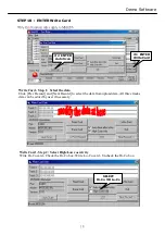
Страница 17: ...Login ID TO Change Login ID Login ID default setting is 0000 1 ENTER Change Login ID 2 ENTER NEW Login ID STEP 8 ENTER UPLOAD TO UPLOAD DATA 3 PRESS UPLOAD 1 UPLOAD DATA STEP 9 ENTER SAVE TO SAVE DATA 1 ENTER SAVE 2 CURRENT FILENAME 17 ...

Страница 18: ...Step 1 Select the data Click Prev Record and Next Record to select the data from upload data All three tracks data can be edited by user if necessary 2 ENTER Auto Scan Write Card Step 2 Select High Low coercivity Write Hi Co card Check the Hi Co box Write Lo Co card Uncheck the Hi Co box SELECT Hi Co OR Lo Co 18 ...

Страница 19: ...o it allows user to uncheck Auto Next after write then select your own data Write Card Step 4 Click Write Card Click Write Card button to write card Click Cancel to stop write card function Write Card Step 5 Finish Write Card Swipe card If the message is Write OK the card has been written successfully If the message is Write Error Please make sure that you have selected right card type Hi Co or Lo...

Страница 20: ...P 12 ENTER Database to erase the memory records of MSR120 Note Always Save the data before Erase STEP 13 ENTER Database to recovery the memory records of MSR120 Note Database must empty ENTER DATABASE CHOOSE RECOVERY DATABASE 1 ENTER DATABASE 2 CHOOSE ERASE DATABASE 20 ...

Страница 21: ...55 Storage Temp 10 60 Humidity 10 90 relative Portable or Any surface RS 232 1 2 3 MC GNET VER 1 2 Communication Protocol Version 1 2 GNET V1 2 Memory Size for Storing Data RTC CLOCK CMOS Serial Flash Memory 512K bytes Up to 2048 records 256 Bytes Record Real Time Clock RTC module and back up capacitor 2048 REC QUEUE USB Interface Full compliance with the USB Specification V 1 1 The device uses a ...

Страница 22: ...r functions 1 POLLING 2 LOGIN LOGOUT 3 DATABASE 4 INFORMATION Also can be expandable Simple format Use ASCII value for each field and use Separator between two Fields GNET Handshaking GNET V1 2 STX CMD CONTENTS CHKSUM CR GNET PACKET STX CMD CONTENTS CHKSUM CR 2 B Start of Text 02 STX REPLY CONTENTS CHKSUM CR ITEM Dec Control Key Function Hex 13 M Carriage Return 0d Ascii Ascii Command Code Ascii A...

Страница 23: ...Information Error Index Table For Reply NAK ACCESS LEVEL COMMAND CODE Topic Error Index 00 01 Access Denied or Password Error Description Command packet is too long DATABASE FILE 02 03 Command packet is empty Command code is out of range 04 05 Illegal Command or Data Database and Register is Empty 06 Record number is out of range 07 08 Check Sum Error Memory Not Enough 0A File Not Exist DATABASE N...

Страница 24: ... Count 4 Bytes Width 0000h 0800h 14 2 READ RECORD BY NUMBER STX G CR STX A CR 02 G 0d Read Record Number 12 TRACK1 ID ABCD TRACK2 ID 2222 TRACK3 ID 3333 02 A 0d EXAMPLE NUMBER 0002 CHKSUM NUMBER Record Count 4 Bytes Width 0000h 07FFh 7A NUMBER DATA DATA Record Data 01h TRACK1 02h TRACK2 03h TRACK3 0002 ABCDEF 123456 654321 DATE TIME WEEK DATA TIME WEEK FEh DATE 20h TIME 20h WEEK 01 02 03 11 10 200...

Страница 25: ... the M command to recover 02 A 0d EXAMPLE 5 RECOVER ALL RECORD STX M CR STX A CR Erase Duration 3 second 02 M 0d Recover all record 02 A 0d EXAMPLE Recover Duration 60 second 6 LOGIN STX L CR STX A CR 02 L 0d Login password 0000 02 A 0d EXAMPLE PASSWORD PASSWORD 4 Characters for Login 0000 Initial value 0000 25 ...

Страница 26: ...ut 02 A 0d EXAMPLE 8 SET PASSWORD STX P CR STX A CR 02 P 0d Set new password 1234 02 A 0d EXAMPLE PASSWORD CHKSUM PASSWORD New four digit password 1234 1A 9 ENTER FIRMWARE MANAGEMENT MODE STX X CR STX A CR 02 X 0d Enter firmware management mode 02 A 0d EXAMPLE 26 ...

Страница 27: ...T CR STX A CR 02 T 0d Get Date 2000 11 8 02 A 0d EXAMPLE Get Time 14 20 31 Thursday YYYYMMDDhhmmssw 200011081420314 12 GET PRODUCT VERSION STX F CR STX A CR ROM Txxxx xxxx Rom serial number ROM No VERSION Year 2000 20xx Month 01 12 Date 01 31 Hour 00 23 Mintue 00 59 Second 00 59 W Week 0 6 Week SUN MON TUE WED THU FRI SAT 0 1 2 3 4 5 6 ROM No Vx xxRm Vx xx Firmware version x xx Rm Modify m times V...

Страница 28: ...EXAMPLE 7 SET REGISTER STX C CR STX A CR REGISTER REGISTER PARAM CHKSUM PARAM Register Address 2 Bytes Width 00h FFh Set Parameters of Register CHKSUM C REGISTER PARAM ROM T0571 8 GET REGISTER STX B CR STX A CR REGSTER REGSTER PARAM CHKSUM PARAM Register Address 2 Bytes Width 00h FFh Set Parameters of Register 28 ...

Страница 29: ...e Format Display Mode User Name Password Register 10h 11h 12h 13h 14h 15h 16h 17h 18h 19h 1Ah 1Bh 1C 1Fh 20 2Fh 30 1FBh 1FC 1FFh Description 00 FFh 0 255 second 00h Auto Power Off FFh Switch Other Real time 2 Characters 00 FFh 00 FFh 0 255 second 00h Off FFh On 00h mm dd yyyy FFh yyyy mm dd other dd mm yyyy 00h Tracks Parallel 01h Credit Card Mode other Tracks Series 16 Characters 4 Characters 29 ...

Страница 30: ...r first 2 Under Windows 98 2000 Me XP put DISK5216 into the cd rom disk driver it will automatically install the USB232 422 485 Driver Software into your Computer by following the steps as below 1 This wizard searches for new drivers for USB Device Click Next Click Next Select this 2 What do you want Windows to do 30 ...

Страница 31: ...USB Driver Setup 3 Select Searching locations for new driver 4 Windows is now ready to install the best driver Give the path location Select this Click Next Device name Path location Click Next 31 ...

Страница 32: ...USB Driver Setup 5 Windows has finished installing the software Finish driver software installation Click Finish 32 ...

Страница 33: ...onnect WAS 1571 Cable into the USB port of the computer and then Click Start Settings Control Panel System Device Manager to see if there are USB232 422 485 COM3 at Ports COM LPT and USB232 422 485 at Universal Serial Bus controllers WAS 1571 is here WAS 1571 connected at COM3 33 ...

Страница 34: ...oftware from your computer Put DISK5216 into the CD ROM drive of the computer and then find and execute Uninstall EXE by following the steps as below 1 Execute Uninstall EXE program 2 Confirm to execute Remove program Execute Uninstall EXE program Click Here 34 ...

Страница 35: ...3 Re boot the Computer after remove program is done Click Yes or click No button for show as below Remove Driver Software 35 ...

Отзывы: