background image

- 17 -

Hardware Installation

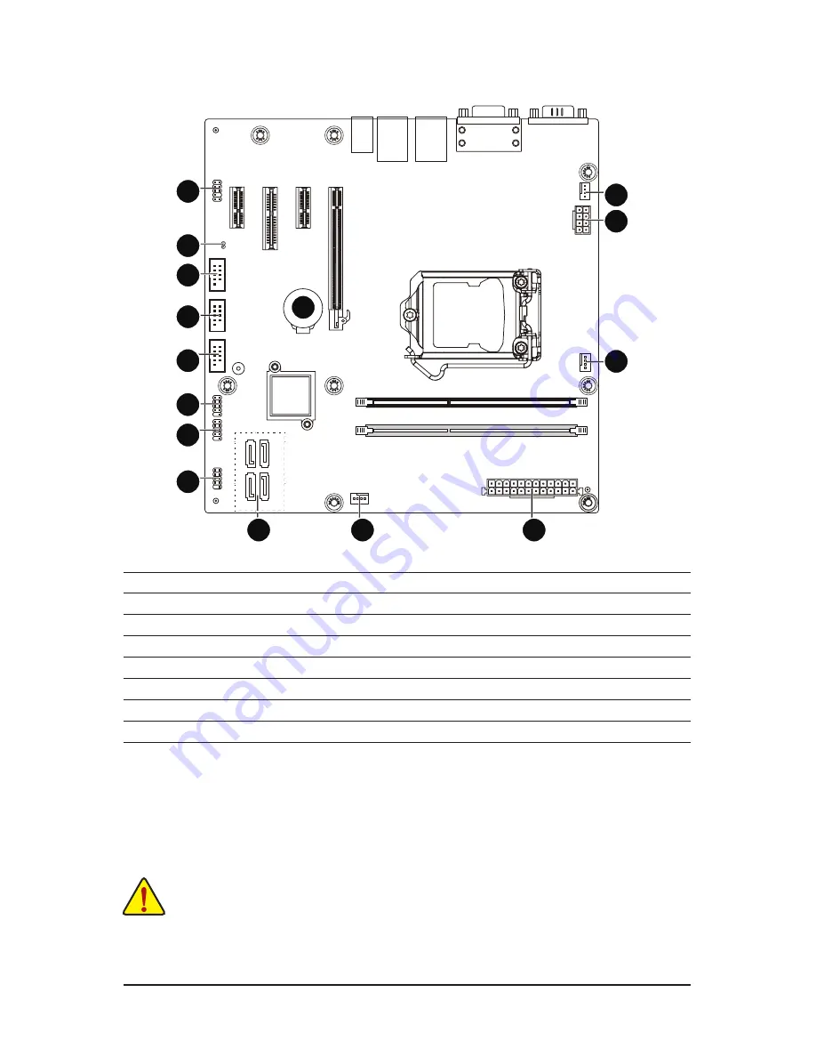
1-6  Internal Connectors

 1)  ATX
 2)  ATX12V_2X4
 3)  SATAIII_0/1/2/3
 4)  CPU_FAN
 5)  SYS_FAN1
 6)  SYS_FAN2
 7)  FUSB2_1
 8)  FUSB2_2

 9)  COM4
 10)  COM3
 11)  COM2
 12)  F_AUDIO
 13)  F_PANEL
 14)  BAT
 15)  CLR_CMOS
  

2

1

3

4

5

6

7

8

9

11

10

12

15

14

13

Read the following guidelines before connecting external devices:

• 

First make sure your devices are compliant with the connectors you wish to connect.

• 

Before installing the devices, be sure to turn off the devices and your computer. Unplug the power 
cord from the power outlet to prevent damage to the devices.

• 

After installing the device and before turning on the computer, make sure the device cable has 

been securely attached to the connector on the motherboard.

Содержание MDH11BM

Страница 1: ...MDH11BM Intel Socket LGA1151 processor motherboard User s Manual Rev 1002 ...

Страница 2: ...nd features in this manual may be made by GIGABYTE without prior notice No part of this manual may be reproduced copied translated transmitted or published in any form or by any means without GIGABYTE s prior written permission Documentation Classifications Inordertoassistintheuseofthisproduct GIGABYTEprovidesthefollowingtypesofdocumentation For detailed product information carefully read the User...

Страница 3: ...mory 14 1 5 Back Panel Connectors 15 1 6 Internal Connectors 17 Chapter 2 BIOS Setup 24 2 1 The Main Menu 26 2 2 Advanced Menu 28 2 2 1 Trusted Computing 29 2 2 2 Super IO Configuration 30 2 2 2 1 Serial Port Configuration for port 1 2 3 4 31 2 2 3 Hardware Monitor 34 2 2 4 S5 RTC Wake Settings 35 2 2 5 CPU Configuration 36 2 2 6 SATA Configuration 39 2 2 7 OS Selection 40 2 3 Chipset Menu 41 2 4 ...

Страница 4: ...river CD I O Shield The box contents above are for reference only and the actual items shall depend on the product package you obtain The box contents are subject to change without notice The motherboard image is for reference only ...

Страница 5: ... 5 MDH11BM Motherboard Layout 2 1 3 4 5 18 6 7 8 9 11 10 12 14 13 16 15 17 20 19 21 22 23 24 25 26 2728 29 ...

Страница 6: ... DIMM slot 2 12 ATX 24 pin main power connector 13 SYS_FAN2 System fan connector 2 14 SATAIII_1 SATA 6Gb s connector 15 SATAIII_3 SATA 6Gb s connector 16 SATAIII_2 SATA 6Gb s connector 17 SATAIII_0 SATA 6Gb s connector 18 F_PANEL Front panel header 19 FUSB2_1 USB 2 0 header 20 FUSB2_2 USB 2 0 header 21 COM4 Serial port cable connector 4 22 COM3 Serial port cable connector 3 23 COM2 Serial port cab...

Страница 7: ... 7 Block Diagram ...

Страница 8: ...y and first touch a metal object to eliminate static electricity Prior to installing the motherboard please have it on top of an antistatic pad or within an electrostatic shielding container Before unplugging the power supply cable from the motherboard make sure the power supply has been turned off Before turning on the power make sure the power supply voltage has been set according to the local v...

Страница 9: ...Slots 1 x PCI Express x16 slot 1 x PCI Express x4 slot running at x2 2 x PCI Express x1 slot Storage Interface 4 x SATA 6Gb s connectors USB 4 x USB 3 0 ports back panel Up to 4 USB 2 0 ports via the USB brackets connected to the internal USB headers Internal Connectors 1 x 8 pin ATX 12V power connector 1 x 24 pin ATX main power connector 4 x SATA 6Gb s connectors 1 x CPU fan header 2 x System fan...

Страница 10: ...peed control Whether the CPU system fan speed control function is supported will depend on the CPU system cooler you install BIOS AMI BIOS Form Factor uATX Form Factor 9 6 inch x 9 6 inch GIGABYTE reserves the right to make any changes to the product specifications and product related information without prior notice ...

Страница 11: ...nment keys on the CPU socket Apply an even and thin layer of thermal grease on the surface of the CPU Do not turn on the computer if the CPU cooler is not installed otherwise overheating and damage of the CPU may occur Set the CPU host frequency in accordance with the CPU specifications It is not recommended that the system bus frequency be set beyond hardware specifications since it does not meet...

Страница 12: ...e other to lightly replace the load plate When replacing the load plate make sure the front end of the load plate is under the shoulder screw NOTE Hold the CPU socket lever by the handle not the lever base portion Step 2 Remove the CPU socket cover as shown Hold your index finger down on the rear grip of the socket cover and use your thumb to lift up the front edge next to the REMOVE mark and then...

Страница 13: ...ng the cooler note the direction of the arrow sign on the male push pin Turning the push pin along the direction of the arrow is for removing the cooler and the opposite direction is for installing it Step 3 Place the cooler atop the CPU aligning the four push pins through the pin holes on the motherboard Push down on the push pins diagonally Step 4 You should hear a click when pushing down each p...

Страница 14: ...in only one direction If you are unable to insert the memory switch the direction 1 4 1 Installing a Memory Before installing a memory module make sure to turn off the computer and unplug the power cord from the power outlet to prevent damage to the memory module Be sure to install DDR4 DIMMs on this motherboard Installation Step Step 1 Insert the DIMM memory module vertically into the DIMM slot a...

Страница 15: ...scribes the states of the LAN port LEDs USB 3 0 Port The USB port supports the USB 3 0 specification Use this port for USB devices such as a USB keyboard mouse USB printer USB flash drive and etc Line In Jack Blue The default line in jack Use this audio jack for line in devices such as an optical drive walkman etc Line Out Jack Green The default line out jack Use this audio jack for a headphone or...

Страница 16: ...aight out from the connector Do not rock it side to side to prevent an electrical short inside the cable connector Activity LED Connection Speed LED LAN Port Activity LED Connection Speed LED State Description Orange 1 Gbps data rate Green 100 Mbps data rate Off 10 Mbps data rate State Description Blinking Data transmission or receiving is occurring Off No data transmission or receiving is occurri...

Страница 17: ... following guidelines before connecting external devices First make sure your devices are compliant with the connectors you wish to connect Before installing the devices be sure to turn off the devices and your computer Unplug the power cord from the power outlet to prevent damage to the devices After installing the device and before turning on the computer make sure the device cable has been secu...

Страница 18: ...ector mainly supplies power to the CPU If the 12V power connector is not connected the computer will not start To meet expansion requirements it is recommended that a power supply that can withstand high power consumption be used 500W or greater If a power supply is used that does not provide the required power the result can lead to an unstable or unbootable system 12 24 1 13 ATX ATX12V_2X4 FDD A...

Страница 19: ...headers possess a foolproof insertion design When connecting a fan cable be sure to connect it in the correct orientation the black connector wire is the ground wire The motherboard supports CPU fan speed control which requires the use of a CPU fan with fan speed control design For optimum heat dissipation it is recommended that a system fan be installed inside the chassis 1 1 Pin No Definition 1 ...

Страница 20: ...B bracket For purchasing the optional USB bracket please contact the local dealer F_USB COMB MODEM Power SUR_CEN PWR_LED CLR_CMOS BIOS_WP CLR_CMOS BIOS_WP CI DPVRM CLR_PWD IR COMB SPDIF_IO F1_1394 F2_1394 GAME SMB_CONN F_AUDIO NEW 1 9 2 10 FUSB2_2 FUSB2_1 F_USB3 Pin No Definition 1 Power 5V 2 Power 5V 3 USB DX 4 USB DY 5 USB DX 6 USB DY 7 GND 8 GND 9 No Pin 10 NC ...

Страница 21: ...2 F_AUDIO Front Panel Audio Header The front panel audio header supports Intel High Definition audio HD and AC 97 audio You may connect your chassis front panel audio module to this header Make sure the wire assignments of the module connector match the pin assignments of the motherboard header Incorrect connection between the module connector and the motherboard header will make the device unable...

Страница 22: ...ssis A front panel module mainly consists of power switch reset switch power LED hard drive activity LED speaker and etc When connecting your chassis front panel module to this header make sure the wire assignments and the pin assignments are matched correctly Pin No Signal Name Definition 1 HD Hard Disk LED Signal anode 2 MPD Power LED Signal anode 3 HD Hard Disk LED Signal cathode 4 MPD Power LE...

Страница 23: ...he battery is replaced with an incorrect model Contact the place of purchase or local dealer if you are not able to replace the battery by yourself or uncertain about the battery model Used batteries must be handled in accordance with local environmental regulations 15 CLR_CMOS Clearing CMOS Jumper Use this jumper to clear the CMOS values e g date information and BIOS configurations and reset the ...

Страница 24: ... with caution Inadequate BIOS flashing may result in system malfunction It is recommended that you not alter the default settings unless you need to to prevent system instability or other unexpected results Inadequately altering the settings may result in system s failure to boot If this occurs try to clear the CMOS values and reset the board to default values Refer to the Restore Defaults section...

Страница 25: ...ation of boot sequence Security Change set or disable supervisor and user password Configuration supervisor password allows you to restrict access to the system and BIOS Setup A supervisor password allows you to make changes in BIOS Setup A user password only allows you to view the BIOS settings but not to make changes Save Exit Save all the changes made in the BIOS Setup program to the CMOS and e...

Страница 26: ... displayed on the bottom line of the Main Menu Submenu Help While in a submenu press F1 to display a help screen General Help of function keys available for the menu Press Esc to exit the help screen Help for each item is in the Item Help block on the right side of the submenu When the system is not stable as usual select the Restore Defaults item to set your system to its defaults The BIOS Setup ...

Страница 27: ...me when the BIOS setup utility was created LAN MAC Address Displays the LAN MAC address information Memory Information Total Memory Display the total memory size of the installed memory ME FW Version Display the ME firmware version System Date Set the date following the weekday month day year format System Time Set the system time following the hour minute second format ...

Страница 28: ... Setup 28 2 2 Advanced Menu The Advanced menu display submenu options for configuring the function of various hardware components Select a submenu item then press Enter to access the related submenu screen ...

Страница 29: ...ted Computing Configuration Security Device Support Select Enabled to activate TPM support feature Options available Enabled Disabled Default setting is Disabled Current Status Information Display current TPM status information ...

Страница 30: ...iguration Press Enter for configuration of advanced items Serial Port 2 Configuration Press Enter for configuration of advanced items Serial Port 3 Configuration Press Enter for configuration of advanced items Serial Port 4 Configuration Press Enter for configuration of advanced items ...

Страница 31: ... 31 BIOS Setup 2 2 2 1 Serial Port Configuration for port 1 2 3 4 ...

Страница 32: ...BIOS Setup 32 ...

Страница 33: ...enabled allows you to configure the serial port settings When set to Disabled displays no configuration for the serial port Options available Enabled Disabled Default setting is Enabled Device Settings Display the specified Serial Port base I O addressand IRQ ...

Страница 34: ...n Option available Enabled Disabled Default setting for CPU FAN Fail Warning is Enabled Default setting for System FAN Fail Warning is Disabled CPU System FAN Speed Control Enable CPU System Fan Speed Control function Option available Normal Full Speed Default setting is Normal System CPU Temperature Displays current CPU temperature CPU System Fan Speed RPM Displays current CPU and system fan spee...

Страница 35: ...led System will wake on the hr min sec specified Default setting is Disabled Wake up hour Note Press and to define the wake up hour Wake up minute Note Press and to define the wake up minute Wake up second Note Press and to define the wake up second Note This item appears when Wake system from S5 is set to Fixed time ...

Страница 36: ...BIOS Setup 36 2 2 5 CPU Configuration ...

Страница 37: ...bled Hardware P State Enable Disable Hardware P State feature Options available Enabled Disabled Default setting is Disabled Intel R SpeedStep tm EISTEnhanced Intel SpeedStep Technology Conventional Intel SpeedStep Technology switches both voltage and frequency in tandem between high and low levels in response to processor load Options available Enabled Disabled Default setting is Enabled Turbo Mo...

Страница 38: ...BIOS Setup 38 CFG lock Enable Disable CFG lock Options available Enabled Disabled Default setting is Disabled ...

Страница 39: ... 39 BIOS Setup 2 2 6 SATA Configuration SATA Port 0 1 2 3 Displays the installed HDD devices information System will automatically detect HDD type ...

Страница 40: ...Isabled Default setting is Disabled LAN EFI driver Enable Disable LAN EFI driver Options available Enabled DIsabled Default setting is Disabled Storage Determines which devices system will boot to Options available Do not launch UEFI Legacy Default setting is UEFI Note You have to select the OS mode in the BIOS setup before installing any OS on your system ...

Страница 41: ...tting is Enabled Onboard LAN Enable Disable onboard LAN controller Options available Enabled Disabled Default setting is Enabled ERP Lowest Power State Mode Enable Disable ERP Lowest Power State Mode Options available Enabled Disabled Default setting is Disabled Restore AC Power Loss This option provides user to set the mode of operation if an AC power loss occurs Power On System power state when ...

Страница 42: ...disable this field a Administrator Password must first be set A user can only access and modify the System Time System Date and Set User Password fields AdministratorPassword Press Enter to configure the Administrator password User Password Press Enter to configure the user password Secure Boot menu Press Enter for configuration of advanced items 2 4 Security Menu The Security menu allows you to s...

Страница 43: ...is way the system knows all the files being loaded before Windows 8 loads and gets to the login screen have not been tampered with Options available Enabled Disabled Default setting is Disabled Secure Boot Mode Note Define the Secure Boot Mode Set this item to Custom to advanced items configuration Option available Standard Custom Default setting is Custom Key Management Press Enter to configure t...

Страница 44: ...x Options available Enabled Disabled Default setting is Disabled Enroll All Factory Default Keys Press Enter to install all factory default keys Save All Secure Boot Variables Press Enter to save all Secure Boot Variables Platform Key PK Press Enter to configure the advanced items Key Exchange Key Press Enter to configure the advanced items Authorized Signature Press Enter to configure the advance...

Страница 45: ...essage if the drive s specified is not bootable Boot Configuration Boot Option Priorities Boot Option 1 2 3 Press Enter to configure the boot priority By default the server searches for boot devices in the following secquence 1 UEFI device 2 Hard drive 3 Network device Hard Drive BBS Priorities Press Enter to configure the boot priority ...

Страница 46: ...Yes No Discard Changes and Exit Discards changes made and close the BIOS setup Options available Yes No Save Changes and Reset Saves changes made and reset the system Options available Yes No Discard Changes and Reset Discards changes made and reset the system Options available Yes No Save Changes Saves changes made in the BIOS setup Options available Yes No Discard Changes Discards changes made i...

Страница 47: ...faults Save to current BIOS settings as user defined default settings Restore as User Defaults Load the user define default settings for all BIOS options Boot Override Allows you to select a device to boot immediately Press Enter on the device you select and select Yes to confirm Your system will restart automatically and boot from that device UEFI Built in in EFI Shell Press Enter on this item to...

Страница 48: ...48 2 7 Flash Your BIOS Follow the steps below to flash your BIOS 1 Put the BIOS files onto a bootable USB stick 2 Press F2 and enter into BIOS setup menu Go to Boot and configure the first boot device to USB disk ...

Страница 49: ... 49 BIOS Setup 3 Press F4 and select Yes to save the configuration 4 Enter the DOS and type cd BIOS file ...

Страница 50: ...BIOS Setup 50 5 Enter FLASH bat to run the batch file 6 Wating for the BIOS update ...

Страница 51: ...n the flashing is completed the screen will show the following message FPT Operation Successful 8 Press Ctrl alt del to exit 9 Reboot he system and press F2 10 Enter into the BIOS setup main menu and check the BIOS version ...

Отзывы: