background image

- 49 -

BIOS Setup

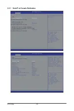
  Legacy OS Redirection Resolution 

(Note)


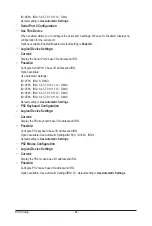
On Legacy OS, the number of Rows and Columns supported redirection.   


Options available: 80x24/80X25. Default setting is 

80x24

.

  Putty KeyPad  

(Note)


Select function FunctionKey and KeyPad on Putty.   


Options available: VT100/LINUX/XTERMR6/SCO/ESCN/VT400. Default setting is 

VT100

.

  Redirection After BIOS POST  

(Note)


This option allows user to enable console redirection after O.S has loaded.  


Options available: Always Enable/Boot Loader. Default setting is 

Always Enable

.

  Out-of-Bnad Mgmt Port


Microsoft Windows Emerency Management Service (EMS) allows for remote management of a Windows 
Server OS through a serial port.


Options available: COM1/COM2. Default setting is 

COM1

.

(Note)  Advanced items prompt when this item is defined.

Содержание MD60-SC0

Страница 1: ...MD60 SC0 MD60 SC1 Dual LGA2011 sockets R3 motherboard for Intel E5 2600 V3 V4 series processors User s Manual Rev 1102 ...

Страница 2: ... of this manual may be reproduced copied translated transmitted or published in any form or by any means without GIGABYTE s prior written permission Documentation Classifications Inordertoassistintheuseofthisproduct GIGABYTEprovidesthefollowingtypesofdocumentations For detailed product information carefully read the User s Manual For more information visit our website at http b2b gigabyte com You ...

Страница 3: ... Internal Connectors 21 1 7 Jumper Settings 34 Chapter 2 BIOS Setup 40 2 1 The Main Menu 42 2 2 Advanced Menu 45 2 2 1 Serial Port Console Redirection 46 2 2 2 PCI Subsystem Settings 50 2 2 2 1 PCI Express Settings 52 2 2 3 Network Stack 54 2 2 4 CSM Configuration 55 2 2 5 Post Report Configuration 57 2 2 6 Trusted Computing 58 2 2 7 USB Configuration 59 2 2 8 Chipset Configuration 60 2 9 SIO Conf...

Страница 4: ...2 3 7 3 1 SATA Mode Options 98 2 3 7 4 USB Configuration 100 2 3 8 Miscellaneous Configuration 101 2 3 9 Server ME Configuration 102 2 3 10 Runtime Error Logging 103 2 3 10 1Whea Setting 104 2 3 10 2Memory Error Enabling 105 2 3 10 3PCI PCI Error Enabling 106 2 4 Server Management Menu 107 2 4 1 System Event Log 109 2 4 2 View FRU Information 110 2 4 3 BMC network configuration 111 2 5 Security Me...

Страница 5: ...r CD Two SAS 6Gb s cables I O Shield The box contents above are for reference only and the actual items shall depend on the product package you obtain The box contents are subject to change without notice The motherboard image is for reference only ...

Страница 6: ...Motherboard Layout 1 2 3 4 5 6 7 8 9 10 11 12 13 14 15 16 17 18 21 22 23 24 25 26 19 20 29 30 27 28 36 35 37 33 34 31 32 40 41 42 43 44 45 47 49 50 51 56 57 58 59 60 61 48 46 52 53 54 55 62 63 64 65 66 67 68 69 70 71 38 39 ...

Страница 7: ...ot 1 for secondary CPU 21 DIMM_P1_F0 Channel 2 slot 0 for secondary CPU 22 DIMM_P1_F1 Channel 2 slot 1 for secondary CPU 23 SYS_FAN4 System fan connector 4 24 SYS_FAN3 System fan connector 3 25 CPU1 Intel LGA2011 Socket R3 Secondary CPU 26 P12V_AUX1 8 pin power connector for primary CPU 27 DIMM_P1_H1 Channel 4 slot 1 for secondary CPU 28 DIMM_P1_H0 Channel 4 slot 0 for secondary CPU 29 DIMM_P1_G1 ...

Страница 8: ...ME_UPDATE ME update jumper 58 BIOS_PWD Clearing Supervisor Password jumper 59 BIOS_RCVR BIOS recovery jumper 60 ME_RCVR ME recovery jumper 61 S3_MASK S3 Power On Select jumper 62 SW_RAID Intel LSI Software RAID Key jumper 63 PCIE_1 PCI Express x16 slot 64 PCIE_2 PCI Express x8 slot Shared bandwidth with PCIE_3 65 PCIE_3 PCI Express x16 slot 66 PCIE_4 PCI Express x8 slot 67 MLAN_LINK BMC Management...

Страница 9: ... 9 Block Diagram ...

Страница 10: ...ry and first touch a metal object to eliminate static electricity Prior to installing the motherboard please have it on top of an antistatic pad or within an electrostatic shielding container Before unplugging the power supply cable from the motherboard make sure the power supply has been turned off Before turning on the power make sure the power supply voltage has been set according to the local ...

Страница 11: ...N 10 100 1000Mpbs LAN port Option Intel XL710 supports 1 x 40GbE LAN port or 4 x 10GbE LAN ports Expansion Slots 2 x PCIe x16 Gen3 x16 bus PCIE_1 PCIE_3 slots 1 x PCIe x8 Gen3 x8 bus PCIE_2 PCIE_4 slot 1 x PCIe mezzanine type T Gen3 x8 bus RAID_SLOT1 RAID_SLOT2 slot or via PCIe switch 1 x PCIe x16 Gen3 x16 bus slot 1 x PCIe x16 Gen3 x8 bus slot 2 x PCIe x8 Gen3 x8 bus slots 1 x PCIe mezzanine type...

Страница 12: ...orts 1 x QSPF LAN port MD60 SC0 Only 3 x RJ 45 ports 1 x 10 100 1000 Mbps dedicated management LAN port 1 x COM port 1 x VGA port 1 x PS 2 connector I O Controller ASPEED AST2400 BMC chip Hardware Monitor System voltage detection CPU System temperature detection CPU System fan speed detection CPU System fan speed control Whether the CPU system fan speed control function is supported will depend on...

Страница 13: ...alignment keys on the CPU socket Apply an even and thin layer of thermal grease on the surface of the CPU Do not turn on the computer if the CPU cooler is not installed otherwise overheating and damage of the CPU may occur Set the CPU host frequency in accordance with the CPU specifications It is not recommended that the system bus frequency be set beyond hardware specifications since it does not ...

Страница 14: ...CPU into the motherboard CPU socket Before installing the CPU make sure to turn off the computer and unplug the power cord from the power outlet to prevent damage to the CPU To protect the socket contacts do not remove the protective plastic cover unless the CPU is inserted into the CPU socket Save the cover properly and replace it if the CPU is removed Step 2 Push the lever closest to the lock ma...

Страница 15: ...er its retention tab The protective plastic cover may pop off from the load plate during the process of engaging the lever Remove the cover Save the cover properly and always replace it when the CPU is not installed Lever B Lever A Step 6 Finally secure lever A under its retention tab to complete the installation of the CPU ...

Страница 16: ...ease on the surface of the installed CPU Step 2 Place the cooler atop the CPU aligning the four mounting screws with the mounting holes on the ILM If your cooler has a fan grill which may cause interference when you tighten the screws remove it first and replace it after tightening the screws Step 3 Use one hand to hold the cooler and the other to tighten the screws in a diagonal sequence with a s...

Страница 17: ... motherboard supports the memory It is recommended that memory of the same capacity brand speed and chips be used Always turn off the computer and unplug the power cord from the power outlet before installing the memory to prevent hardware damage Memory modules have a foolproof design A memory module can be installed in only one direction If you are unable to insert the memory switch the direction...

Страница 18: ...M module Note For dual channel operation DIMMs must be installed in matched pairs Step 3 Reverse the installation steps when you wish to remove the DIMM module 2 2 1 1 4 3 DIMM Population Table Two Slots Channel RDIMM Population Configuration Within a Channel NOTE DDR4 2400MHz is only available on Intel Xeon E5 2600 V4 processor Type Ranks Per DIMM and Data Width Speed MT s Slot Per Channel SPC an...

Страница 19: ...n QSFP LAN Port MD60 SC0 Only The QSFP LAN port provides Internet connection at up to 40 Gbps data rate based on the LAN chipset The following describes the states of the LAN port LEDs RJ 45 LAN Ports Gigabit Ethernet LAN Ports The Gigabit Ethernet LAN port provides Internet connection at up to 1 Gbps data rate The following describes the states of the LAN port LEDs KVM Server Management 10 100 10...

Страница 20: ...g Data transmission or receiving is occurring Off No data transmission or receiving is occurring Link Activity LED Port 0 Link Activity LED Speed LED Port 1 Link Activity LED QSFP LAN Port 10G 40G LAN Port With Intel XL710 LAN Chipset QSFP LAN Port 1000 10G LAN Port With Intel 82599ES LAN Chipset Link Activity LED QSFP Speed LED State Description Green On 40 Gbps data rate Yellow On 10 Gbps data r...

Страница 21: ...S_FAN2 System Fan 9 SYS_FAN3 System Fan 10 SYS_FAN4 System Fan 11 SYS_FAN5 System Fan 12 SATA4 13 SATA5 14 SAS0 1 2 3 4 5 6 7 15 MINI_CN1 16 MINI_CN2 17 SAS_SGP1 18 SAS_SGP2 19 F_USB3 20 FP_1 21 BP_1 22 COM2 23 TPM 24 LAN4_ACT 25 LAN3_ACT 26 MLAN_LINK 27 MLAN_ACT 28 IPMB 29 LED_BMC 30 BAT 1 2 3 4 6 7 8 9 10 11 21 19 22 24 25 20 14 184 30 13 5 12 17 15 16 26 27 28 29 23 ...

Страница 22: ...e connectors you wish to connect Before installing the devices be sure to turn off the devices and your computer Unplug the power cord from the power outlet to prevent damage to the devices After installing the device and before turning on the computer make sure the device cable has been securely attached to the connector on the motherboard ...

Страница 23: ... The 12V power connector mainly supplies power to the CPU If the 12V power connector is not connected the computer will not start Pin No Definition 1 GND 2 GND 3 GND 4 GND 5 12V 6 12V 7 12V 8 12V To meet expansion requirements it is recommended that a power supply that can withstand high power consumption be used 500W or greater If a power supply is used that does not provide the required power th...

Страница 24: ...th fan speed control design For optimum heat dissipation it is recommended that a system fan be installed inside the chassis Be sure to connect fan cables to the fan headers to prevent your CPU and system from overheating Overheating may result in damage to the CPU or the system may hang These fan headers are not configuration jumper blocks Do not place a jumper cap on the headers Pin No Definitio...

Страница 25: ...nform to SATA 6Gb s standard and are compatible with SATA 3Gb s and 1 5Gb s standard Each SATA connector supports a single SATA device Please see page 35 for SATA DOM jumper setting Pin No Definition 1 GND 2 TXP 3 TXN 4 GND 5 RXN 6 RXP 7 GND Normal Mode Pin No Definition 1 GND 2 TXP 3 TXN 4 GND 5 RXN 6 RXP 7 P5V SATA DOM Mode SATA5 SATA4 14 SAS0 SAS1 SAS2 SAS3 SAS4 SAS5 SAS6 SAS7 SAS cable connect...

Страница 26: ... four SATA device MINI_CN1 MINI_CN2 B1 A1 A18 B18 Pin No Definition A1 GND A2 RX0 A3 RX0 A4 GND A5 RX1 A6 RX1 A7 GND A8 SIB7 A9 SIB3 A10 SIB4 A11 SIB5 A12 GND A13 RX2 A14 RX2 A15 GND A16 RX3 A17 RX3 A18 GND Pin No Definition B1 GND B2 TX0 B3 TX0 B4 GND B5 TX1 B6 TX1 B7 GND B8 SIB0 B9 SIB1 B10 SIB2 B11 SIB6 B12 GND B13 TX2 B14 TX2 B15 GND B16 TX3 B17 TX3 A18 GND ...

Страница 27: ...k drives HDDs to store and retrieve data 7 1 8 2 Pin No Definition 1 DATAIN 2 No Pin 3 DATAOUT 4 GND 5 GND 6 LOAD 7 NC 8 CLOCK SAS_SGP2 SAS_SGP1 19 F_USB3 USB 3 0 Header The headers conform to USB 3 0 specification Each USB header can provide two USB ports via an optional USB bracket For purchasing the optional USB bracket please contact the local dealer Pin No Definition 1 Power 2 IntA_P1_SSRX 3 ...

Страница 28: ...ments are matched correctly Pin No Signal Name Definition 1 PWR_LED Power LED Anode 2 5VSB Front Panel Power 3 KEY Key 4 ID_LED System ID LED Anode 5 PWR_LED Power LED Cathode 6 ID_LED System ID LED Cathode 7 HDD_LED HDD Activity LED Anode 8 SYS_STATUS System Fault LED Anode 9 HDD_LED HDD Activity LED Cathode 10 SYS_STATUS System Fault LED Cathode 11 PWR_BTN Power Switch 12 LAN1_LED NIC 1 Activity...

Страница 29: ...No Definition 1 BP_SGP_CLK 2 NC 3 BP_SGP_GLD 4 FAN_GATE_N 5 BP_SGP_DOUT 6 GND 7 KEY 8 Rreset 9 GND 10 BP_LED_A_N 11 BP_LED_G_N 12 GND 13 BP_SGP_DIN 14 NC 15 GND 16 SMB_BP_DATA 17 GND 18 SMB_BP_CLK 19 P_3V3_AUX 20 BMC_ACK 21 P_3V3_AUX 22 BMC_REQ 23 GND 24 KEY 25 BP_PRESENSE 26 GND ...

Страница 30: ...l COM port cable please contact the local dealer 1 2 1 2 13 14 9 10 Pin No Definition 1 NDCD 2 NSIN 3 NSOUT 4 NDTR 5 GND 6 NDSR 7 NRTS 8 NCTS 9 NRI 10 No Pin Pin No Definition 1 CLK_33M_TPM 2 P_3V3_AUX 3 LPC_RST 4 P3V3 5 LPC_LAD0 6 IRQ_SERIAL 7 LPC_LAD1 8 TPM_DET_N 9 LPC_LAD2 10 NC 11 LPC_LAD3 12 GND 13 LPC_FRAME_N 14 GND 23 TPM TPM Module Connector ...

Страница 31: ...allation Pin No Definition 1 LED 2 LED Pin No Definition 1 Link 1G 2 Link 100 Mbps 1 1 2 2 24 25 LAN4_ACT LAN3_ACT LAN4 LAN3 Active LED Header 26 MLAN_LINK Management LAN Port Link LED Header LAN4_ACT LAN3_ACT MLAN_LINK ...

Страница 32: ...Hardware Installation 32 28 IPMB IPMB Connector Pin No Definition 1 Clock 2 GND 3 Data 3 1 Pin No Definition 1 Active 2 GND 1 2 27 MLAN_ACT Management LAN Port Active LED Header MLAN_ACT ...

Страница 33: ...ace the battery with an equivalent one Danger of explosion if the battery is replaced with an incorrect model Contact the place of purchase or local dealer if you are not able to replace the battery by yourself or uncertain about the battery model When installing the battery note the orientation of the positive side and the negative side of the battery the positive side should face up Used batteri...

Страница 34: ...Hardware Installation 34 1 7 Jumper Settings 4 5 6 7 8 9 1 2 3 10 11 1 SATA_DOM4 2 SATA_DOM5 3 CLR_CMOS 4 CASE_OPEN 5 ME_UPDATE 6 BIOS_PWD 7 BIOS_RCVR 8 ME_RCVR 9 S3_MASK 10 SW_RAID 11 BMC_FRB ...

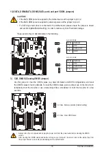
Страница 35: ...n 1 P5V 2 SATA5 Pin7 3 GND For SATA_DOM5 1 1 1 1 1 1 3 CLR_CMOS Clearing CMOS Jumper Use this jumper to clear the CMOS values e g date information and BIOS configurations and reset the CMOS values to factory defaults To clear the CMOS values place a jumper cap on the two pins to temporarily short the two pins or use a metal object like a screwdriver to touch the two pins for a few seconds 1 2 Clos...

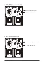
Страница 36: ...SE_OPEN Chassis intrusion Header Open Normal operation Default setting Closed Enable chassis intrusion alter 5 ME_UPDATE ME Update Jumper 1 2 Close Normal operation Default setting 2 3 Close ME recovery mode 1 1 CASE_OPEN ME_UPDATE ...

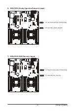
Страница 37: ...BIOS recovery mode 1 2 Close Normal operation Default setting 7 BIOS_RCVR BIOS Recovery Jumper 6 BIOS_PWD Clearing Supervisor Password Jumper 2 3 Close Skip supervisor password 1 2 Close Normal operation Default setting 1 1 BIOS_PWD BIOS_RCVR ...

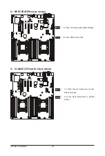
Страница 38: ...ery Jumper 1 2 Close Normal operation Default setting 2 3 Close ME recovery mode 1 1 9 S3_MASK S3 Power On Select Jumper 2 3 Close Keep initial power on Default setting 1 2 Close Stop an initial power on when BMC is not ready 1 1 ME_RCVR S3_MASK ...

Страница 39: ... 39 Hardware Installation 1 1 11 BMC_FRB Force to Stop FRB Timer Jumper 10 SW_RAID Intel LSI Software RAID Key Header 1 2 Close Normal operation Default setting 2 3 Close Force to Stop FRB Timer SW_RAID ...

Страница 40: ...caution Inadequate BIOS flashing may result in system malfunction It is recommended that you not alter the default settings unless you need to to prevent system instability or other unexpected results Inadequately altering the settings may result in system s failure to boot If this occurs try to clear the CMOS values and reset the board to default values Refer to the Exit section in this chapter o...

Страница 41: ...bled setup menus Security Change set or disable supervisor and user password Configuration supervisor password allows you to restrict access to the system and BIOS Setup A supervisor password allows you to make changes in BIOS Setup A user password only allows you to view the BIOS settings but not to make changes Boot This setup page provides items for configuration of boot sequence Exit Save all ...

Страница 42: ... displayed on the bottom line of the Main Menu Submenu Help While in a submenu press F1 to display a help screen General Help of function keys available for the menu Press Esc to exit the help screen Help for each item is in the Item Help block on the right side of the submenu When the system is not stable as usual select the Restore Defaults item to set your system to its defaults The BIOS Setup ...

Страница 43: ...ersion Display BMC firmware version information SDR Reversion Display the SDR version information FRU Version Display the FRU version information Processor Information CPU Brand String Max CPU Speed CPU Signature Processors Core Microcode Patch Displays the technical specifications for the installed processor Memory Information Total Memory Display the total memory size of the installed memory Mem...

Страница 44: ...rmation LAN1 LAN2 LAN3 LAN4 MAC Address Display LAN1 LAN2 LAN LAN4 MAC address information System Date Set the date following the weekday month day year format System Time Set the system time following the hour minute second format ...

Страница 45: ...BIOS Setup 2 2 Advanced Menu The Advanced menu display submenu options for configuring the function of various hardware components Select a submenu item then press Enter to access the related submenu screen ...

Страница 46: ...BIOS Setup 46 2 2 1 Serial Port Console Redirection ...

Страница 47: ... 47 BIOS Setup ...

Страница 48: ...Space Parity bit is always 0 Mark and Space Parity do not allow for error detection Options available None Even Odd Mark Space Default setting is None Stop Bits Stop bits indicate the end of a serial data packet A start bit indicates the beginning The standard setting is 1 stop bit Communication with slow devices may require more than 1 stop bit Options available 1 2 Default setting is 1 Flow Cont...

Страница 49: ...6 SCO ESCN VT400 Default setting is VT100 Redirection After BIOS POST Note This option allows user to enable console redirection after O S has loaded Options available Always Enable Boot Loader Default setting is Always Enable Out of Bnad Mgmt Port Microsoft Windows Emerency Management Service EMS allows for remote management of a Windows Server OS through a serial port Options available COM1 COM2...

Страница 50: ...ialize device expansion ROM Options available Enabled Disabled Default setting is Enabled PCI Devices Common Settings PCI Latency Timer Value to be programmed into PCI Latency Timer Register Options available 32 PCI Bus Clocks 64 PCI Bus Clocks 96 PCI Bus Clocks 128 PCI Bus Clocks 160 PCI Bus Clocks 192 PCI Bus Clocks 224 PCI Bus Clocks 248 PCI Bus Clocks Default setting is 32 PCI Bus Clocks VGA P...

Страница 51: ...tem has SR IOV capable PCIe Devices this option enables or disables Single Root IO Virtualization Support Options available Enabled Disabled Default setting is Disabled PCI Express Settings Press Enter for configuration of advanced items ...

Страница 52: ...ble Enabled Disabled Default setting is Enabled Maximum Playload Set maximum playload for PCI Express Device or allow system BIOS to select the value Options available Auto 128 Bytes 256 Bytes 512 Bytes 1024 Bytes 2048 Bytes 4096 Bytes Default setting is Auto PCI Express Link Register Settings Extended Synch Wnen this feature is enabled the system will allow generation of Extended Synchronization ...

Страница 53: ... in Link Status register Press keys to increase or decrease the desired values Value rang is from 10 to 10000 us Unpopulated Links When this item is set to Disable Link the system will operate power save feature for those unpopulated PCI Express links Options available Keep Link ON Disable Link Default setting is Keep Link ON ...

Страница 54: ...ure Options available Enabled DIsabled Default setting is Enabled Ipv6 PXE Support Note Enable Disable Ipv6 PXE feature Options available Enabled DIsabled Default setting is Enabled PXE boot wait time Note Press keys to increase or decrease the desired values Media detect time Note Press keys to increase or decrease the desired values Note This item appears when Network Stack is set to Enabled ...

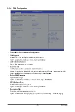
Страница 55: ...ys Do not allow disabling GA20 this option is useful when any RT code is executed above 1MB Options available Upon Request Always Default setting is Upon Request Option ROM Messages Option ROM Messages Options available Force BIOS Keep Current Default setting is Force BIOS INT19 Endless Retry Enabled Allowed headless retry boot Options available Enabled Disabled Default setting is Enabled Boot opt...

Страница 56: ...cution UEFI and Legacy Storage OpROM Options available Do not launch UEFI Legacy Default setting is Legacy Video Controls the execution UEFI and Legacy Video OpROM Options available Do not launch UEFI Legacy Default setting is Legacy Other PCI devices Determines OpROM execution policy for devices other than network Storage or Video Options available UEFI Legacy Default setting is UEFI ...

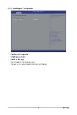
Страница 57: ...S Setup 2 2 5 Post Report Configuration Post Report Configuration Error Message Report Post Error Message Enable Disable Info Error Message support Options available Enabled Disabled Default setting is Enabled ...

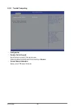
Страница 58: ...ed Computing Configuration Security Device Support Select Enabled to activate TPM support feature Options available Enabled Disabled Default setting is Disabled Current Status Information Display current TPM status information ...

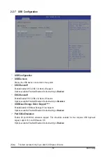
Страница 59: ...ction Options available Enabled Disabled Default setting is Disabled USB Mass Storage Driver Support Note Enable Disable USB Mass Storage Driver Support Options available Enabled Disabled Default setting is Enabled Port 60 64 Emulation Enable I O port 60h 64h emulation support This should be enabled for the complete USB Keyboard Legacy support for non USB aware OS Options available Enabled Disable...

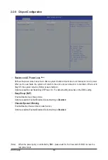
Страница 60: ... system remains off after power shutdown Options available Last State Stay Off Power On The default setting depends on the BMC setting Deep Sleep EuP Enable Disable Deep Sleep mode Options available Enabled Disabled Default setting is Disabled Chassis Opened Warning Enable Disable Chassis intrusion alter funtion Options available Enabled Disabled Default setting is Disabled Note When the power pol...

Страница 61: ... 61 BIOS Setup 2 9 SIO Configuration ...

Страница 62: ...BIOS Setup 62 ...

Страница 63: ...erial Port 1 Configuration Use This Device When enabled allows you to configure the serial port 1 settings When set to Disabled displays no configuration for the serial port Options available Enabled Disabled Default setting is Enabled Logical Device Settings Current Display the Serial Port 1 base I O addressand IRQ Possible Configure Serial Port 1 base I O addressand IRQ Option available Use Auto...

Страница 64: ...IO 2F8h IRQ 3 DMA IO 3F8h IRQ 3 4 5 7 9 10 11 12 DMA IO 2F8h IRQ 3 4 5 7 9 10 11 12 DMA IO 3E8h IRQ 3 4 5 7 9 10 11 12 DMA IO 2E8h IRQ 3 4 5 7 9 10 11 12 DMA Default setting is Use Automatic Settings PS2 Keyboard Configuration Logical Device Settings Current Display the PS2 keyboard base I O addressand IRQ Possible Configure PS2 keyboard base I O addressand IRQ Option available Use Automatic Setti...

Страница 65: ...onfiguration iSCSI Initiator Name Add an Attempts Press Enter for configuration of advanced items Delete Attempts Press Enter for configuration of advanced items Change Attempt Order Press Enter for configuration of advanced items ...

Страница 66: ...enu Intel RC Setup menu displays submenu options for configuring the function of North Bridge and South Bridge Select a submenu item then press Enter to access the related submenu screen RC Revision Display Intel RC version information ...

Страница 67: ... 67 BIOS Setup 2 3 1 Processor Configuration ...

Страница 68: ...ble Disable Intel Trusted Execution Technology support function Options available Enabled Disabled Default setting is Disabled VMX Vanderpool Technology Enable Disable Vanderpool Technology This will take effect after rebooting the system Options available Enabled Disabled Default setting is Enabled Enable SMX Intel Safer Mode Extensions Technology Enable Disblae Intel Safer Mode Extensions SMX su...

Страница 69: ... Options available Disabled 8 16 24 32 40 48 56 64 72 80 88 96 104 112 Default setting is 32 X2APIC Options available Enabled Disabled Default setting is Disabled AES NI Enable Disable AES NI Intel Advanced Encryption Standard New Instructions support function Options available Enabled Disabled Default setting is Enabled ...

Страница 70: ...BIOS Setup 70 2 3 1 1 Pre Socket Configuration ...

Страница 71: ... Socket 0 1 Configuration Press Enter for configuration of advanced items Cores Enabled for CPU socket 0 1 Number of Cores to enable 0 means all cores 14 Cores is available Press the numeric keys to adjust desired values ...

Страница 72: ...le Energy Efficient Custom Default setting is Energy Efficient Config TDP Options available Enabled Disabled Default setting is Disabled CPU P State Control Press Enter for configuration of advanced items CPU C State Control Press Enter for configuration of advanced items CPU T State Control Press Enter for configuration of advanced items ...

Страница 73: ...d Disabled Default setting is Enabled P state coordination In HW_ALL mode the processor hardware is responsible for coordinating the P state among logical processors dependencies The OS is responsible for keeping the P state request up to date on all logical processors In SW_ALL mode the OS Power Manager is responsible for coordinating the P state among logical processors with dependencies and mus...

Страница 74: ... C6 non Retention state CPU C3 C6 Report Allows you to determine whether to let the CPU enter C3 C6 mode in system halt state When enabled the CPU core frequency and voltage will be reduced during system halt state to decrease power consumption The C3 C6 state is a more enhanced power saving state than C1 Options available Enabled Disabled Default setting for C3 is Disabled default setting for C6 ...

Страница 75: ... 75 BIOS Setup 2 3 2 3 CPU T State Control ACPI T States Enable Disable CPU throttling by OS Thorttling reduces power comsumption Options available Enabled Disabled Default setting is Enabled ...

Страница 76: ...ommon RefCode Configuration Common RefCode Configuration Isoc Mode Options available Auto Enabled Disabled Default setting is Auto Numa Non Uniform Memory Access Options available Enabled Disabled Default setting is Enabled ...

Страница 77: ... 77 BIOS Setup 2 3 4 QPI Configuration ...

Страница 78: ... for configuration of advanced items QPI Status Press Enter to view QPI status Link Speed Mode Options available Slow Fast Default setting is Fast Link Frequency Select Options available 6 4GB s 8 0GB s 9 6GB s Auto Auto Limited Default setting is Auto ...

Страница 79: ...quency Options available Auto 1333 1400 1600 1800 1867 2000 2133 Default setting is Auto ECC Support Options available Auto Disabled Enabled Default setting is Auto Rank Margin Tool Options available Auto Disabled Enabled Default setting is Auto RMT Pattern Length Display RMT Pattern Length SPD Write Lock Options available Enabled Disabled Default setting is Enabled Memory Topology Press Enter for...

Страница 80: ...BIOS Setup 80 Memory Map Press Enter for configuration of advanced items Memory RAS Configuration Press Enter for configuration of advanced items ...

Страница 81: ... 81 BIOS Setup 2 3 5 1 Memory Topology ...

Страница 82: ...Throttling Mode Configure Thermal Throttling Mode Select OLTT or CLTT mode Options available Disabled CLTT Mode Default setting is CLTT Mode MEMHOT Throttling Mode Options available Disabled Output only Input only Default setting is Input only ...

Страница 83: ...cal memory below 4GB Options available Disabled Enabled Default setting is Disabled Channel Interleaving Options available Auto 1 way Interleave 2 way Interleave 3 way Interleave 4 way Interleave Default setting is Auto Rank Interleaving Options available Auto 1 way Interleave 2 way Interleave 4 way Interleave 8 way Interleave Default setting is Auto ...

Страница 84: ... enabled Sparing will be selected Options available Disable Mirror Lockstep Mode Default setting is Disabled Lockstep x4 DIMMs Options available Auto Disabled Enabled Default setting is Auto Memory Rank Sparing Options available Disabled Enabled Default setting is Disabled Correctable Error Threshold Press keys to increase or decrease the desired values ...

Страница 85: ...tures Set this option to allow DFX Lock Bits to remain clear Options available Enabled Disabled Default setting is Disabled IOAT Configuration Press Enter for configuration of advanced items Intel VT for Directed I O VT d Press Enter for configuration of advanced items ...

Страница 86: ...ble IOAT Control to enable disable IOAT Intel I O Acceleration Technology device Options available Enabled Disabled Default setting is Disabled No Snoop Enable Disable PCI Express Device No Snoop option Options available Enabled Disabled Default setting is Disabled ...

Страница 87: ... O VT d Enable Disable Intel VT for Directed I O VT d support function Options available Enabled Disabled Default setting is Enabled Interrupt Remapping Enable Disable interrupt remapping support function Options available Enabled Disabled Default setting is Enabled Coherency Suuport Non Isoch Options available Enabled Disabled Default setting is Enabled Coherency Suuport Isoch Options available E...

Страница 88: ...evices Press Enter for configuration of advanced items PCH sSATA Configuration Press Enter for configuration of advanced items PCH SATA Configuration Press Enter for configuration of advanced items USB Configuration Press Enter for configuration of advanced items ...

Страница 89: ... 89 BIOS Setup 2 3 7 1 PCH Devices PCH CRID Enable Disable Intel Compatible Revision ID Options available Enabled Disabled Default setting is Disabled ...

Страница 90: ...BIOS Setup 90 2 3 7 2 PCH sSATA Configuration ...

Страница 91: ...he RAID setup utility at boot time ACHI Mode When set to AHCI the SATA controller enables its AHCI functionality Then the RAID function is disabled and cannot be access the RAID setup utility at boot time Options available IDE RAID ACHI Disabled Default setting is ACHI SATA Test Mode Enable Disable SATA Test Mode Options available Enabled Disabled Default setting is Disabled SATA Mode options Note...

Страница 92: ...available Enabled Disabled Default setting is Enabled Hot Plug for Port 0 1 2 3 Note Enable Disable HDD Hot Plug function Options available Enabled Disabled Default setting is Disabled Configured as eSATA Note Display Hot Plug supported information Spin Up Device for Port 0 1 2 3 Note On an edge detect from 0 to 1 the PCH starts a COM reset initialization to the device Options available Enabled Di...

Страница 93: ... Setup 2 3 7 2 1 SATA Mode Options SATA LED locate When this option is enabled LED SGPIO hardware is attached Options available Enabled Disabled Default setting is Enabled When SATA Type is set to IDE AHCI Mode ...

Страница 94: ...ons available Enabled Disabled Default setting is Enabled RAID Option ROM UI banner Options available Enabled Disabled Default setting is Enabled IRRT Only on ESATA Options available Enabled Disabled Default setting is Enabled Smart Response Technology Enable Disable Intel Smart Response Technology support function Options available Enabled Disabled Default setting is Enabled RAID OROM prompt dela...

Страница 95: ... 95 BIOS Setup 2 3 7 3 PCH SATA Configuration ...

Страница 96: ...lity at boot time ACHI Mode When set to AHCI the SATA controller enables its AHCI functionality Then the RAID function is disabled and cannot be access the RAID setup utility at boot time Options available IDE RAID ACHI Disabled Default setting is ACHI SATA Test Mode Enable Disable SATA Test Mode Options available Enabled Disabled Default setting is Disabled SATA RSTe Boot Info Note 1 Enable Disab...

Страница 97: ...detect HDD type Port 0 1 2 3 4 5 Enable Disable Port 0 1 2 3 device Options available Enabled Disabled Default setting is Enabled Hot Plug for Port 0 1 2 3 4 5 Note Enable Disable HDD Hot Plug function Options available Enabled Disabled Default setting is Disabled Configured as eSATA Note Display Hot Plug supported information Spin Up Device for Port 0 1 2 3 4 5 Note On an edge detect from 0 to 1 ...

Страница 98: ...up 98 2 3 7 3 1 SATA Mode Options SATA LED locate When this option is enabled LED SGPIO hardware is attached Options available Enabled Disabled Default setting is Enabled When SATA Type is set to IDE AHCI Mode ...

Страница 99: ...Recovery Technology support function Options available Enabled Disabled Default setting is Enabled RAID Option ROM UI banner Options available Enabled Disabled Default setting is Enabled Smart Response Technology Enable Disable Intel Smart Response Technology support function Options available Enabled Disabled Default setting is Enabled RAID OROM prompt delay Options available 2 Seconds 4 Seconds ...

Страница 100: ...dition work on USB host conteoller and root ports for faster enumeration Options available Enabled Disabled Default setting is Disabled xHCI Mode Enable Disable xHCI USB 3 0 support function Options available Smart Auto Enabled Disabled Default setting is Smart Auto ...

Страница 101: ... 101 BIOS Setup 2 3 8 Miscellaneous Configuration Miscellaneous Configuration Active Video Select active Video type Options available Onboard Device Offboard Device Default setting is Offboard Device ...

Страница 102: ...ware Version Display Recovery Firmware Version information ME Firmware Features Display ME Firmware features information ME Firmware Status 1 2 Display ME Firmware status information Current State for ME Firmware Display ME Firmware current status information Error Code for ME Firmware Display ME Firmware status error code MCTP Bus Owner Configure MCTP Bus Owner ...

Страница 103: ... setting is Enabled S W Error Injection Support Enable Disable software injection error logging function Options available Enabled Disabled Default setting is Disabled Whea Settings Press Enter for configuration of advanced items Memory Error Enabling Press Enter for configuration of advanced items PCI PCI Error Enabling Press Enter for configuration of advanced items ...

Страница 104: ...BIOS Setup 104 2 3 10 1 Whea Setting WHEA Support Windows Hardware Error Architecture Enable Disable WHEA Support Options available Enabled Disabled Default setting is Enabled ...

Страница 105: ... Error Enabling Memory Error Enabling Un Correctable Errors disable Memory Options available Enabled Disabled Default setting is Disabled Memory corrected Errors enabling Options available Enabled Disabled Default setting is Disabled ...

Страница 106: ...ting is Enabled Fatal Error Enable Options available Enabled Disabled Default setting is Enabled Enable SERR propagation When this item is set to enabled PCI bus system error SERR is generated and is routed to NMI Options available Yes No Default setting is Yes Enable PERR propagation When this item is set to Yes PCI bus parity error PERR is generated and is routed to NMI Options available Yes No ...

Страница 107: ...wn Default setting is Do Nothing Please note that this item is configurable when FRB 2 Timer is set to Enabled OS Watchdog Timer Enable Disable OS Watchdog Timer function Options available Enabled Disabled Default setting is Disabled OS Wtd Timer Timeout Configure OS Watchdog Timer Options available 5 minutes 10 minutes 15 minutes 20 minutes Default setting is 10 minutes Please note that this item...

Страница 108: ...etup 108 System Event Log Press Enter for configuration of advanced items View FRU Information Press Enter to view the advanced items BMC network configuration Press Enter for configuration of advanced items ...

Страница 109: ...se options for erasing SEL Options available No Yes On next reset Yes On every reset Default setting is No When SEL is Full Choose options for reactions to a full SEL Options available Do Nothing Erase Immediately Default setting is Do Nothing Custom EFI Logging Options Log EFI Status Codes Enable Disable the logging of EFI Status Codes if not already converted to legacy Options available Disabled...

Страница 110: ...BIOS Setup 110 2 4 2 View FRU Information The FRU page is a simple display page for basic system ID information as well as System product information Items on this window are non configurable ...

Страница 111: ...thing option willnot modify any BMC network parameters during BIOS phase Options available Unspecified Static DynamicBmcDhcp Default setting is Unspecified Static Station IP Address Display IP Address information Subnet mask Display Subnet Mask information Please note that the IP address must be in three digitals for example 192 168 000 001 Router IP address Display the Router IP Address informati...

Страница 112: ...strator password User Password Press Enter to configure the user password Secure Boot menu Press Enter for configuration of advanced items 2 5 Security Menu The Security menu allows you to safeguard and protect the system from unauthorized use by setting up access passwords ...

Страница 113: ... running during the booting process to be pre signed with valid digital certificates This way the system knows all the files being loaded before Windows 8 loads and gets to the login screen have not been tampered with When set to Standard it will automatically load the Secure Boot keys form the BIOS databases When set to Custom you can customize the Secure Boot settings and manually load its keys ...

Страница 114: ...to install all factory default keys Save All Secure Boot Variables Press Enter to save all Secure Boot Variables Platform Key PK Display the status of Platform Key Delete the PK Press Enter to delete the existed PK Once the PK is deleted all the system s Secure Boot keys will not be activated Set new PK File Press Enter to configure a new PK Key Exchange Key Database KEK Display the status of Plat...

Страница 115: ... Enter to delete the db from your system Set new DB Press Enter to configure a new db Append aVar to DB Press Enter to load additional db from a storage devices Forbidden Signature Database DBX Display the status of Forbidden Signature Database Delete the DBX Press Enter to delete the dbx from your system Set DBX from File Press Enter to configure a new dbx Append Var to DBX Press Enter to load ad...

Страница 116: ...te waiting Press the numberic keys to input the desired value Bootup NumLock State Enable or Disable Bootup NumLock function Options available On Off Default setting is On Quiet Boot Enables or disables showing the logo during POST Options available Enabled Disabled Default setting is Enabled Boot Option Priorities Boot Option 1 2 3 4 Press Enter to configure the boot priority By default the serve...

Страница 117: ... 117 BIOS Setup Network Device BBS Priorities Press Enter to configure the boot priority Hard Drive BBS Priorities Press Enter to configure the boot priority ...

Страница 118: ...ns available Yes No Save Options Save Changes Saves changes made in the BIOS setup Options available Yes No Discard Changes Discards changes made and close the BIOS setup Options available Yes No Restore Defaults Loads the default settings for all BIOS setup parameters Setup Defaults are quite demanding in terms of resources consumption If you are using low speed memory chips or other kinds of low...

Страница 119: ... 119 BIOS Setup Boot Override Press Enter to configure the device as the boot up drive UEFI Built in in EFI Shell Press Enter on this item to Launch EFI Shell from filesystem device ...

Страница 120: ...x30 PEI_MEMORY_INSTALLED 0x31 PEI_CPU_INIT 0x32 PEI_CPU_CACHE_INIT 0x33 PEI_CPU_BSP_SELECT 0x34 PEI_CPU_AP_INIT 0x35 PEI_CPU_SMM_INIT 0x36 PEI_MEM_NB_INIT 0x37 reserved for NB 0x38 0x3A PEI_MEM_SB_INIT 0x3B reserved for SB 0x3C 0x3E reserved for OEM use 0x3F 0x4E PEI_DXE_IPL_STARTED 0x4F Recovery PEI_RECOVERY_AUTO 0xF0 PEI_RECOVERY_USER 0xF1 PEI_RECOVERY_STARTED 0xF2 PEI_RECOVERY_CAPSULE_FOUND 0xF...

Страница 121: ...IVERS 0x91 DXE_PCI_BUS_BEGIN 0x92 DXE_PCI_BUS_HPC_INIT 0x93 DXE_PCI_BUS_ENUM 0x94 DXE_PCI_BUS_REQUEST_RESOURCES 0x95 DXE_PCI_BUS_ASSIGN_RESOURCES 0x96 DXE_CON_OUT_CONNECT 0x97 DXE_CON_IN_CONNECT 0x98 DXE_SIO_INIT 0x99 DXE_USB_BEGIN 0x9A DXE_USB_RESET 0x9B DXE_USB_DETECT 0x9C DXE_USB_ENABLE 0x9D reserved for AMI use 0x9E 0x9F reserved for AML use 0xA0 DXE_IDE_BEGIN 0xA1 DXE_IDE_RESET 0xA2 DXE_IDE_D...

Страница 122: ... 0x50 PEI_MEMORY_INVALID_SPEED 0x50 PEI_MEMORY_SPD_FAIL 0x51 PEI_MEMORY_INVALID_SIZE 0x52 PEI_MEMORY_MISMATCH 0x52 PEI_MEMORY_NOT_DETECTED 0x53 PEI_MEMORY_NONE_USEFUL 0x53 PEI_MEMORY_ERROR 0x54 PEI_MEMORY_NOT_INSTALLED 0x55 PEI_CPU_INVALID_TYPE 0x56 PEI_CPU_INVALID_SPEED 0x56 PEI_CPU_MISMATCH 0x57 PEI_CPU_SELF_TEST_FAILED 0x58 PEI_CPU_CACHE_ERROR 0x58 PEI_CPU_MICROCODE_UPDATE_FAILED 0x59 PEI_CPU_N...

Страница 123: ..._STATUS_CODE DXE_CPU_ERROR 0xD0 DXE_NB_ERROR 0xD1 DXE_SB_ERROR 0xD2 DXE_ARCH_PROTOCOL_NOT_AVAILABLE 0xD3 DXE_PCI_BUS_OUT_OF_RESOURCES 0xD4 DXE_LEGACY_OPROM_NO_SPACE 0xD5 DXE_NO_CON_OUT 0xD6 DXE_NO_CON_IN 0xD7 DXE_INVALID_PASSWORD 0xD8 DXE_BOOT_OPTION_LOAD_ERROR 0xD9 DXE_BOOT_OPTION_FAILED 0xDA DXE_FLASH_UPDATE_FAILED 0xDB DXE_RESET_NOT_AVAILABLE 0xDC reserved for AMI use 0xDE 0xDF ...

Страница 124: ... Firmware Volume was not found 4 Recovery failed 4 S3 Resume failed 7 Reset PPI is not available of Beeps Description 1 Invalid password 4 Some of the Architectural Protocols are not available 5 No Console Output Devices are found 5 No Console Input Devices are found 6 Flash update is failed 7 Reset protocol is not available 2 9 BIOS POST Beep code 2 9 1 PEI Beep Codes 2 9 2 DEX Beep Codes ...

Страница 125: ...ck can be used to restore the BIOS to a working state To restore your BIOS please follow the instructions listed below Recovery Instruction 1 Change xxx ROM to amiboot rom 2 Copy amiboot rom and AFUDOS exe to USB diskette 3 Setting BIOS Recovery jump to enabled status 4 Boot into BIOS recovery 5 Run Proceed with flash update 6 BIOS update BIOS_RCVR ...

Страница 126: ... we at GIGABYTE are continuing our efforts to develop products that do not use internationally banned toxic chemicals Waste Electrical Electronic Equipment WEEE Directive Statement GIGABYTE will fulfill the national laws as interpreted from the 2002 96 EC WEEE Waste Electrical and Elec tronic Equipment directive The WEEE Directive specifies the treatment collection recycling and disposal of electr...

Страница 127: ...ntainers this product was delivered in and by disposing of or recycling used batteries properly With your help we can reduce the amount of natural resources needed to produce electrical and electronic equipment minimize the use of landfills for the disposal of end of life products and generally improve our quality of life by ensuring that potentially hazardous substances are not released into the ...

Отзывы: