E
.2
5.
05
.1
1
Start-up
15
21. Start-up
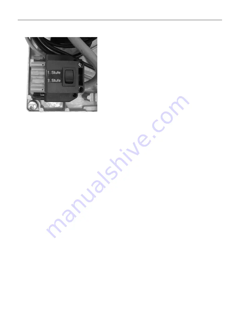
For burner commissioning, the first stage can be set manually
using the switch on the socket unit.
The switch on the socket unit must be at the position 2nd stage
during operation. The air throttle is closed in standstill. In stage 1,
ignition and pre-ventilation (approx. 15 secs.) is activated after
the air throttle opens. Then the solenoid valve opens and
releases the oil for stage 1. After flame formation and completion
of the ignition phase, the burner switches over to the 2nd stage
after 60 secs. Then, set the required pump pressure in accord-
ance with the nozzle selection table (see adjustment table). Fol-
lowing a brief period of operation in stage 2, measurements
(CO
2
, soot accumulation and exhaust air temperature) can be
performed. If necessary, the air can be readjusted with the adjust-
ing screw and/or positioning motor ST2.
Important:
Set dimension "A" only in the 2nd stage!
In order to check the burning in the 1st stage, set the switch on the socket unit to
1st stage. Set the air flow at cam ST1 of the positioning motor.
After calibration of the burner, refasten the hood of the positioning motor. Switch over the switch on
the connector to position 2nd stage. On completion of work, set the control thermostat 2nd stage lower than
the control thermostat 1st stage!
22. Calibration of the boiler-burner
A precise calibration is necessary for a burning that is low in emissions and energy saving. For this purpose, a
burner is assigned to the boiler in accordance with the work ranges and taking into account the combustion
chamber resistance. The immersion depth of the burner pipe to the respective burner chamber is set via the slid-
ing flange.
23. Flue connection
The prerequisite for a faultless functioning of the firing system is a correctly dimensioned flue. Dimensioning is
effected in accordance with DIN EN 13384, Part 1 in consideration of DIN 18160 and the local regulations and
based on the boiler and burner outputs.
Refer to the technical information and installation instructions of the heat generator for further information.
24. Exhaust gas thermometer
For exhaust gas temperature monitoring the heating system should be equipped with an exhaust gas thermom-
eter. The higher the exhaust gas temperature, the greater the exhaust gas loss. Rising exhaust gas tempera-
tures indicate increasing deposits that will reduce the degree of combustion efficiency.
In the event of an increasing exhaust gas temperature, have the heating system cleaned and readjusted by a
specialist.
Содержание GL20-Z-L-LN
Страница 20: ...E 25 05 11 20 Explosion drawings spare parts lists 28 Explosion drawings spare parts lists GL20 1 LN ZBZ_1 517...
Страница 22: ...E 25 05 11 22 Explosion drawings spare parts lists GL20 2 LN ZBZ_1 518...
Страница 24: ...E 25 05 11 24 Explosion drawings spare parts lists GL20 3 LN ZBZ_1 519...


