


3
unit assembly & set-up (cont.)
•
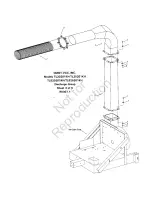
Slip one end of metal discharge hose (3:6) onto
barrel of discharge stack.
•
Secure hose in place with squeeze ring (3:7),
tightening all bolts securely enough to dimple
hose against barrel of stack and thereby
prevent slippage of hose on stack assembly.
INTAKE ASSEMBLY (ALL UNITS)
•
Slip one hose clamp (2:9) onto one end of
intake hose (2:8), then slip end of hose onto
intake flange barrel (2:5), located in front of
impeller housing. Tighten clamps securely.
•
Slip Hose support band (2:10) about half-way
up the length of the hose, with eye clip facing
up.
•
Slip one hose clamp onto free end of intake
hose, followed by Intake Nozzle (2:11) with
handle pointed upwards and toward hose.
Tighten clamps securely.
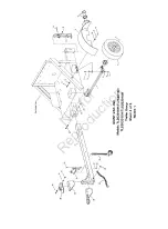
HOSE SUPPORT BOOM ASSEMBLY (ALL UNITS)
•
Attach yoke end of Threaded spring guide (5:5)
to second thru hole of horizontal boom member
(5:2) with one 1/2-13 x 3” hex bolt (5:3),
securing with 1/2-13 lock nut (5:4). Do not over
tighten lock nut. Note: Be sure spring guide
and chain eye at end of boom are both toward
bottom of boom member.
•
Attach horizontal boom member to vertical
boom member (5:1) with one 1/2-13 x 3” hex
bolt, securing with 1/2-13 lock nut. Do not over
tighten lock nut. Be sure spring guide is toward
base of vertical boom member.
•
Remove 3/4” hex nut and flat washer (5:6-7)
from bottom of threaded spring guide. Slip
thread down through hole in base of vertical
boom member, securing with same hardware
as previously removed.
Not
for
Reproduction
Содержание 20hp Series
Страница 15: ...N o t f o r R e p r o d u c t i o n ...
Страница 17: ...N o t f o r R e p r o d u c t i o n ...
Страница 19: ...N o t f o r R e p r o d u c t i o n ...
Страница 21: ...N o t f o r R e p r o d u c t i o n ...
Страница 23: ...N o t f o r R e p r o d u c t i o n ...