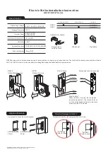

Installation Instruction
(2)
Mark the
latch position line
(3)
Mount
the
supplied
installation
template
and
align
to
the
marked line
(4)
Drill and cut the hole according
to
the
template
supplied
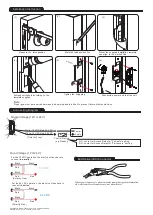
(5)
Tighten
the
fixing plug
Connect the
power
and
test
the
unit
Measure
the
latch position
(1)
Note:
Proper gap must be reserved between the doorstop and latch bolt to prevent failure of solenoid valve.
Butt Splice(IDC) Connector
Using crimper or pliers and pressing the header
of connector down to even position
12 VDC
24 VDC
For the 12 VDC operation, the electric strikes have to
connect
in parallel
.
For the 24 VDC operation, the electric strikes have to
connect
in series
.
Black
Black
Black
Black
Black
Black
Red
Red
Red
Red
Red
Red
Connecting Diagram
Single
Voltage
(12
V
or
24
V
)
Dual
Voltage
(12
V
/24
V
)
Connecting Diagram
+
+
-
-
White
:
12 V
DC
Red
:
24 V
DC
White
:
12 VDC
Red
:
24 VDC
(Polarity Free)
Power
supply
Control Device
(e.g. Reader)
N.C. contact or Access Relay for "Fail-safe" setting
N.O. contact or Access Relay for "Fail-secure” setting
(Polarity Free)
(Polarity Free)
+
-
-
+
(6)
Copyright
©
Gianni
Industries
,
Inc
.
All rights reserved.
P-MU-GK320
Ver.C Publish:2010.11.22


