


20
19
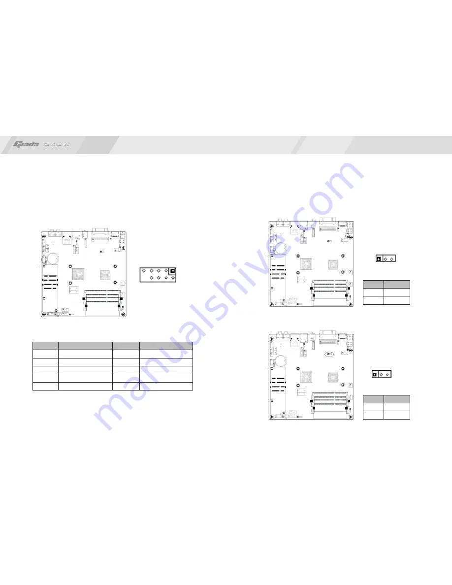
1-2
2-3
Disable
Enable
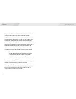
PIN
Definition
RXD1
DTR1
DSR1
CTS1
NC
DCD1
TXD1
GND
RTS1
RI1
2
4
6
8
10
1
3
5
7
9
1
4.13 JP7 (Back ADJ linear and PWM option)
To connect two channel speakers.
4.14 JP8 (U3 software flash pin)
NOTE:
Please set the jumper to 1-2pin after programing
Signal
PIN
Signal
PIN
1-2
2-3
PWM
Linear
1
2
9
PIN
Definition
4.12 COMA1(Front end COM port)
Use a cable to connect an outlay IR receive module.
www.giadatech.com
1


