background image

- 12 -

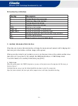
B. Function Keys definitions

Hot Key

Description

(Up key) Move to the previous item

(Down key) Move to the next item

(Left key) Move to the left item

(Right key) Move to the right item

ESC

Exit the current interface

Page Up

Change the setup state, or add the values

Page Down

Change the setup state, or deduct the values

F1

Display the information of the current function Keys definitions.

F9

Load the optimized values

F10

Save the settings and exit the CMOS SETUP

C. Auxiliary information Main interface

When the system enters the main interface of Setup, the major selected contents will be displayed at
the lower part of the interface with the change of the options.

When you set the value for each column, you can view the preset value of the column and the values
that can be set if you press F2, for example, the BIOS default values or CMOS Setup values.
To exit the interface for auxiliary information, press [ESC].

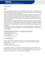
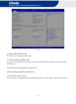
1) Main menu

When the system enters the CMOS Setup menu, you can see the main menu on the upper part of the screen, as
shown in Figure 1.
In this main menu, you can use the left and right direction keys to select the setup items.
Once the item is selected, the lower part of the computer screen will show the details of setting.

Содержание DM5

Страница 1: ......

Страница 2: ...y legal responsibility for the consequences of infringement use of this manual Safety Notice Read the user manual carefully before setting up the Giada product Disconnect the power cord before installing the internal components Most electronic components are sensitive to static electrical charge please wear a wrist grounding strap when installing the internal components Don t disconnect the power ...

Страница 3: ...llation Steps 6 3 1 Memory Installation 7 3 2 WiFi 3G 4G Installation 8 3 3 MSATA Installation 8 3 4 2 5 SATA Installation 9 3 5 SIM Card Installation 10 4 BIOS Setup 10 4 1 Main Standard CMOS Setup 13 4 2 Advanced Advanced BIOS Setup 14 4 2 1 ACPI Setting 15 4 2 2 Power Configuration 16 4 2 3 CPU Configuration 17 4 2 4 CMS Configuration 18 4 2 5 Network State Configuration 20 ...

Страница 4: ...on 30 4 2 10 MAC IPV6 Network Configuration 30 4 3 Security Setup 31 4 4 Boot Menu 32 4 5 Save Exit 34 5 JAHC Introduction 35 5 1 Auto Power On 35 5 2 JAHC Software 37 5 2 1 JAHC Software Functions 37 5 2 2 JAHC Software Installation Guide 37 5 2 3 Startup and Shutdown Time Setup 40 5 3 Watchdog API and Instruction 42 ...

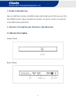
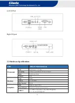
Страница 5: ... middle range R1305G processor With three HDMI2 0 display outputs it supports 4K resolution The player is suitable to be applied in various digital signage applications 2 Interface Description and Hardware Specifications 2 1 Interface Description Front I O Port Rear I O Port ...

Страница 6: ...RyzenTM R1305G Frequency 1 5GHz up to 2 8GHz 2Cores 4Thread BIOS AMI Source Code Chipset SOC Memory Type DDR4 Socket 2 x SO DIMM Max Capacity 32 GB Graphics GPU RadeonTM Vega 3 GPU Graphic Engine DirectX12 OpenGL 4 4 OpenCL1 2 HDMI2 0 3 x HDMI2 0 Supporting 2 x 4K 3840x2160 60Hz or 3 x 2K 1920x1080 60Hz ...

Страница 7: ...e for WiFi BT 3G 4G Storage mSATA 1 x Full size mSATA SATA 1 x 2 5 SATA JAHC JAHC Watchdog Auto power on IR Remote Control RTC Wake On Lan Operation System OS Windows 10 64 bit Linux Power Power Type DC IN Input Voltage 19V 3 42A Mechanical Construction Metal Mounting Desk VESA Mounting JZ183 Dimension W x D x H 189 6mm x 148 3mm x 26mm Color Black Environment Operating Temperature 0 40 at 0 7m s ...

Страница 8: ...opening the case How to open the top cover and bottom cover Unscrew the four screws and remove the top cover SO DIMM 1 and 2 5 SATA slot are on top side Unscrew the four screws push the bottom cover and remove it SO DIMM 2 mini PCIE slot for WIFI 3G 4G mini PCIE slot for MSATA and SIM card slot are on bottom side ...

Страница 9: ... product only supports DDR4 SO DIMM memory modules 1 Locate the SO DIMM slot on the board 2 Gently insert the module into the slot in a 45 degree angle 3 Carefully push down the memory module until it snaps into the locking mechanism ...

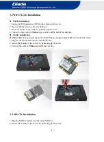
Страница 10: ...Main and grey cable to AUX Install the antenna 3G 4G Installation Defaut SMA connector and cable is for WIFI Please change to 3G 4G SMA connector and cable 1 Plug the 3G 4G module into the mini PCIE slot 2 Secure the module to the carrier by tightening up the screw 3 Connect the cable to Main and install the antenna 3 3 MSATA Installation 1 Plug the MSATA module into the mini PCIE slot 2 Secure th...

Страница 11: ... 9 3 4 2 5 SATA Installation 1 Plug 2 5 SATA into the slot 2 Tighten up the two screws from another bottom side ...

Страница 12: ... 10 3 5 SIM Card Installation This product supports standard SIM card with the size of 25mm 15mm 1 Open the SIM card holder and pull it up 2 Insert the SIM card 3 Lock the card holder ...

Страница 13: ...tup of BIOS plays a key role in stably running the system and optimizing its performance The CMOS Setup will save the set parameters in the built in CMOS SRAM on the motherboard When the power is shut off the lithium battery on the motherboard will provide continuously power to CMOS SRAM The BIOS setup program will allow you to configure the following items 1 HD drive and peripheral devices 2 Vide...

Страница 14: ... enters the main interface of Setup the major selected contents will be displayed at the lower part of the interface with the change of the options When you set the value for each column you can view the preset value of the column and the values that can be set if you press F2 for example the BIOS default values or CMOS Setup values To exit the interface for auxiliary information press ESC 1 Main ...

Страница 15: ...for setting the advanced functions provided by BIOS such as specifications of PCIe facilities CPU HDD etc 3 Security set the administrator user password 4 Boot startup configuration characteristics 5 Save Exit option of exit This item includes load optimal defaults load failsafe defaults value discard changes discard changes and exit ...

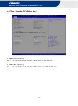
Страница 16: ...dard CMOS setting 1 System time hh mm ss Use this item to set the time for the computer with the format as HH MM SS 2 System date mm dd yy Use this item to set the date for the computer with the format as week MM DD YY ...

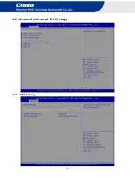
Страница 17: ... 15 4 2 Advanced Advanced BIOS setup 4 2 1 ACPI Setting ...

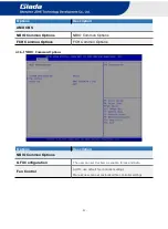
Страница 18: ...led Hibernation ACPI Sleep state You can use the ACPI Sleep state option to control system hibernation Suspend Disabled Disable system Suspend S3 Suspend to RAM Enable S3 Suspend to RAM 4 2 2 Power Configuration OEM Menu Functions Description OEM Configuration Resume On Lan Wake On LAN Function Disabled The WOL is disabled by default Enabled ...

Страница 19: ...l wake on the hr min sec specified Select DynamicTime System will wake on the current time Increase minute s JAHC Enabled JEHE Active Hardware Control JAHC management system includes both hardware Micro Control Unit MCU and software JAHC Technology Manager Disabled The JAHC is disable by default Enabled 4 2 3 CPU Configuration ...

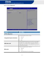
Страница 20: ...nt is PState by default NX Mode Enable disable No execute page protection Function SVM Mode Enabled disable CPU virtualization Node 0 information View Memory Information related to node 0 4 2 4 CMS Configuration CSM Options Description Compatibility Support Module Configuration CSM Support Enabled The CSM support function is enable by default Disabled ...

Страница 21: ...only It only supports legacy mode UEFI only It only supports UEFI mode Option ROM Execution Network Network ROM Boot Do not launch Do not Boot UEFI It will support UEFI mode network ROM Legacy It will support legacy mode network ROM Storage Storage ROM Boot Do not launch Do not Boot UEFI It will support UEFI mode storage ROM Legacy It will support legacy mode storage ROM Video Video ROM Boot UEFI ...

Страница 22: ... 20 4 2 5 Network State Configuration You can enable or disable IPV4 PXE and IPV6 PXE Boot function via Network Stack 4 2 6 AMD CBS Settings ...

Страница 23: ...ommon Options FCH Common Options 4 2 6 1 NBIO Common Options Options Description NBIO Common Options GFX Configuration The user can set this item as enable forces and Auto Fan Control AUTO use default fan controller settings Manual user can set customized fan controller settings ...

Страница 24: ...r Disabled Forces Auto UMA Above 4G If requested UMA frame buffer size can t be fit under 4GB or the system has enough available memory above 4GB this option may be set to TRUE to allow UMA frame buffer size to be allocated successfully NB Azalia Enabled Integrate HD Audio controller Disabled Forces Auto NB Azalia item is auto by default ...

Страница 25: ...ture Medium Temperature High Temperature High Temperature Critical Temperature Critical Temperature Low PWM Low PWM 0 100 Medium PWM Medium PWM 0 100 High PWM High PWM 0 100 Temperature Hysteresis Temperature Hysteresis PWM Frequency 100HZ 25KHZ This item is 25KHZ by default Fan Polarity Negative Positive The Fan Polarity value is positive by default ...

Страница 26: ... 24 4 2 6 2 FCH Common Option ...

Страница 27: ...t state to go to when power is re applied after a power failure Always Off If set it as Always Off it means the system will remain shutdown state Power On If set it as Power On State it means the system will be power on automatically Previous If set it as previous it means the system will keep State of last setup Uart Configuration Options Uart 1 Enable Disabled Enabled This item is enabled by def...

Страница 28: ... 26 FCH Common Options Description Uart 1 Legacy Options Disabled COM1 0x3F8 4 2 7 AMD PBS Settings ...

Страница 29: ...ons Description AMD Firmware Version Primary Video Adapter Int Graphics IGD This item is enabled by default Select IGD used by the internal graphics device Ext Graphics PEG Select PEG used by the extend graphics device ...

Страница 30: ... 28 4 2 8 VLAN Configuration ...

Страница 31: ...e and TPM Clear function Platform Hierarchy Disable or Enable the Platform Hierarchy Storage Hierarchy Disable or Enable the Storage Hierarchy Endorsement Hierarchy Disable or Enable the Endorsement Hierarchy TPM2 0 UEFI spec version TPM2 0 UEFI Options TCG_1_2 or TCG_2 The version is TCG_2 by default Physical Presence Spec Version You can choose 1 2 or 1 3 The version is 1 3 by default TPM 20 Int...

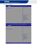
Страница 32: ... 30 4 2 9 MAC IPV4 Network Configuration Configuration IPV4 network parameters 4 2 10 MAC IPV6 Network Configuration ...

Страница 33: ...em the password will be required to be entered before both the system guides and entering to the setup program of BIOS If it is set as Setup the password will be required to be entered only before the system entering to the setup program of BIOS To delete the password press Enter in the popped up window that requires to enter the password Then information for confirmation will appear on the screen...

Страница 34: ...p NumLock State Options are OFF and ON In other words this item can be used to set the state of Num Lock after entering the system It can be set according to user s needs and doesn t affect the performance of the computer Quiet Boot If this item is set as Enabled the system can be started within five seconds and some detection items will be ignored The options are Disabled and Enabled FIXED BOOT O...

Страница 35: ...ice Boot Option 11 The eleventh boot device UEFI Hard Disk Drive BBS Priorities You can set and management UEFI hard device after enabling this option UEFI Application Boot Priorities You can set and management UEFI hard disk after enabling this option UEFI USB Drive BBS Priorities You can set and management UEFI USB device after enabling this option Hard Drive BBS Priorities You can set and manag...

Страница 36: ...t Save Exit Item Description Save Options Save Changes and Reset Save all changes and exit Discard Changes and Reset Give up the settings and exit Restore Defaults Recover it to default Boot Override Whole Boot devices ...

Страница 37: ... set up automatic startup and shutdown one week as a circle 3 Watchdog timer It is a built in API interface 4 Infrared remote control Optional IR controller 5 1 How to set up Auto power on function Automatically reboot when power on The function of automatically reboot when power on is controlled by hardware You can enable it by switching the JAHC button to on If you cannot find the physical switc...

Страница 38: ... 36 b Select Advanced Power Configuration JAHC Enable Enabled c Press F10 to save change exit after select JAHC enabled option ...

Страница 39: ... No additional settings needed 5 2 2 JAHC software installation guide System Requirements a Giada player with JAHC function b Switch the JAHC button to on or enable it in BIOS if there is no physical button on the chassis c Supported operation system Windows 10 64bit Linux 64bit How to install JAHC software Please download the JAHC EXE from Giada website www giadatech com then follow up below step...

Страница 40: ... 38 b Click Next button to continue the installation c Select Create a desktop shortcut and click Next button ...

Страница 41: ... 39 d Click Install button to continue the installation ...

Страница 42: ...software automatically after finishing the installation Notice The JAHC will be added into boot item when it is installed It will start up when system boot up 5 2 3 Startup shutdown time setup After install the JAHC software double click the JAHC icon on taskbar and the setup menu will pop up ...

Страница 43: ...time and shutdown time Caution If the interval from shutdown time to next resume time is less than 3 minutes the system will not shut down Click Cancel button to restore the time settings and cancel the shutdown status Click X button to hide the menu You can find it on taskbar Right click the JAHC icon on taskbar and select exit to exit the software Shutdown caution the shutdown caution will pop u...

Страница 44: ...g box will pop up You can click Delay button and set up the time to delay the shutdown or click Cancel button to cancel the shutdown 5 3 Watchdog API and instruction Please contact Giada FAE email support giadatech com for watchdog API software and instruction ...

Страница 45: ... 43 ...
Отзывы: