


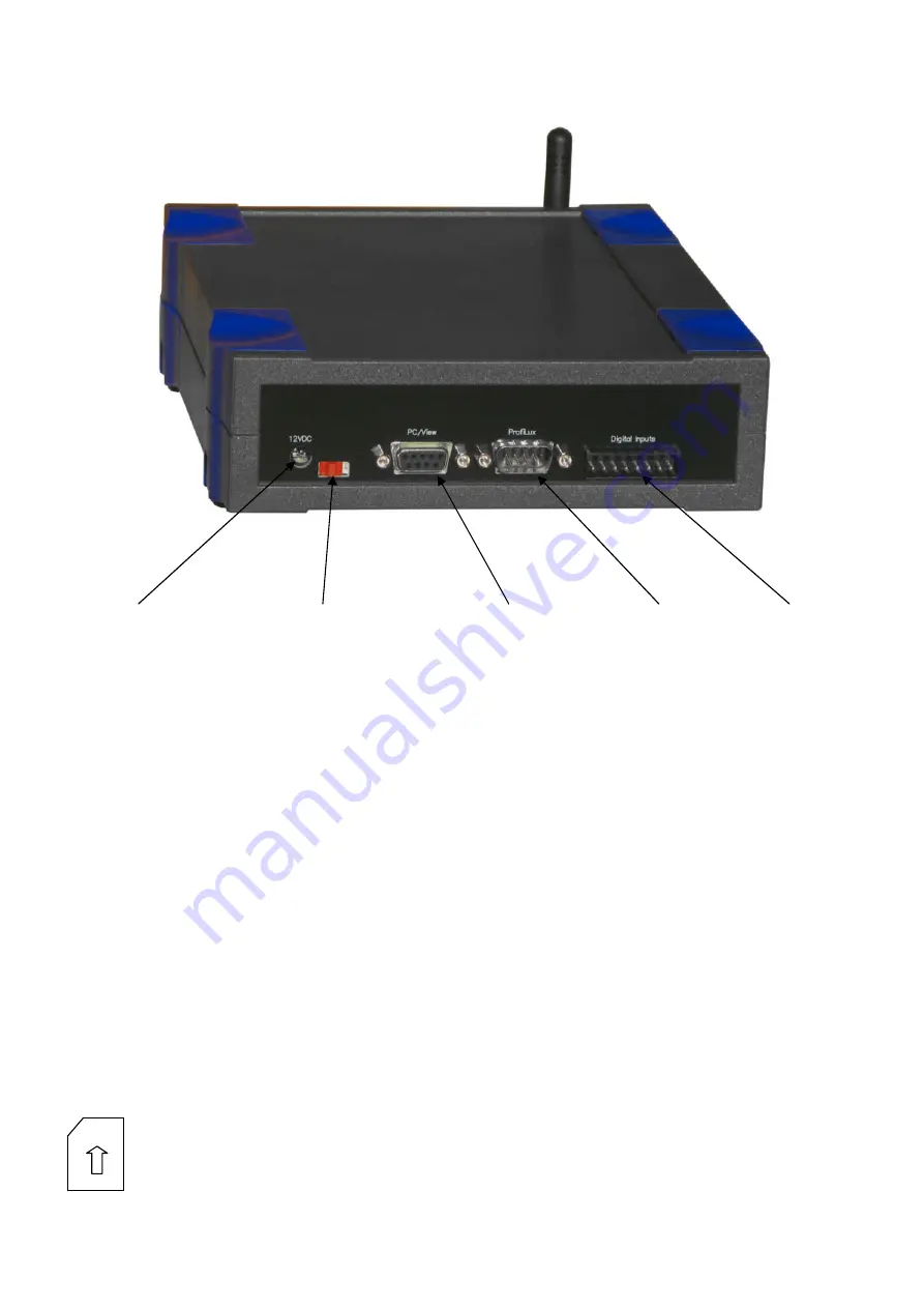
3 Connections
Power supply
Switch (here switched off)
Port for PC or
ProfiLux
View
Port for
ProfiLux
Digital inputs
Due to transport reasons the antenna has been shipped separately. Screw the antenna onto the provided socket.
Insert the DC-jack of the AC/DC adaptor into the power supply connector of the SMS-Module and the mains voltage plug into a
wall outlet.
If a serial connection cable between
ProfiLux
and PC is present then remove it from the
ProfiLux
and plug it instead into the port
PC/View
of the SMS-Module.
If the plug of a
ProfiLux View
is connected to the
ProfiLux
then remove it from the
ProfiLux
and plug it into the port
PC/View
of
the
SMS-Module
.
Connect the RS232-socket of the
ProfiLux
with the RS232-plug
ProfiLux
of the
SMS-module
. Use for this purpose the shipped
cable.
Important hints:
Don’t swap the serial cables! The shipped cable can only be used for the connection of the
ProfiLux
with the
SMS-module
. A standard serial connection cable must be used between
SMS-module
and PC!
The connected
ProfiLux
must have firmware 4.04 at least!
If the communication with the PC should be made with a communication card (
PLM-USB
,
PLM-LAN
,
PLM-
WLAN
or
PLM-RS485
) then the “router”-function must be enabled (see
ProfiLux
manual, section
“communication”) in order to be able to communicate with the
SMS-module
.
During a firmware update via RS232 the
ProfiLux
must be connected to the PC directly – the
SMS-module
must
not be between them!
4 Operation
First you should insert the SIM-card (see left). The card must be pushed in firmly until it locks. If you want to
remove the card again later you have to push the card until it unlocks and it will jump out. Don’t remove the SIM-
card during operation!
Содержание ProfiLux SMS-Module
Страница 8: ......