GHIELMETTI 674.114.913.02 Скачать руководство пользователя страница 18


GHIELMETTI AG –  7UW50 -  Technische Dokumentation 

ROR/09.02.2021 

Page 18 of 19 

16


Ordering Data 

GKV 2×11×14 621 SS K 
674.114.913.02 

17


Service condition and repairs 

WARNING! The relay is not designed for use in resi-dential, commercial or light-industrial 
environment as defined in EN 50081. 

Repair  of  the  device  is  not  recommended.  If  the  device  defect  please  send  back  to 
GHIELMETTI AG or contact us for support. 
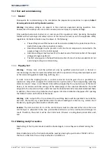
17.1


Replace the mini-fuse 


Select a replacement fuse 5 x 20 mm. Ensure that the rated value, time lag (medium slow) and code 

letters are correct. Fuse: 0.5A / M (5x20mm) 


Prepare area of work: provide conductive surface 

for the module.


Open housing cover. 


Warning : Hazardous voltages can be present in the device even after disconnection of the supply 
voltage or after removal of the module from the housing (storage capacitors)! 

Caution : Electrostatic discharges via the component connections, the PCB tracks or the connecting 
pins  of  the  modules  must  be  avoided  under  all  circumstances  by  previously  touching  an  earthed 
metal surface. 


Unscrew the fixing screws in the rear wall and on the side walls  of the housing. 


Pull out the module and place it onto the conductive surface. 


Remove blown fuse from the holder on the PCB. 


Fit new fuse into the holder. 


Insert module into the housing. 


Close housing cover. 


Switch on the device again. If a power supply failure is still signalled, a fault or short-circuit 
is present in the internal power supply. The device should be returned to the factory. 


Содержание 674.114.913.02

Страница 1: ...Tripping matrix for Generator Protection Systems GKV 2x11x14 621 SSK 7UW50 250 VDC Part No 674 114 913 02 Manual Edition 04 2020...

Страница 2: ...ecting the Tripping Matrix 8 11 1Auxiliary output screw mount connectors 9 12 Installation instruction 10 12 1Unpacking and repacking 10 12 2Preparations 10 12 2 1Mounting and connections 10 12 2 2Che...

Страница 3: ...formance at the factory according to the specifications given for the system in this manual However before putting the device into operation we kindly ask you to read this manual and act according to...

Страница 4: ...rvicing adjustments maintenance or repair of this product may be performed by qualified personnel only 6 Disclaimer This instruction manual does not purport to cover all details in equipment nor to pr...

Страница 5: ...le are used for programming the matrix the reliability being attained by generous over rating with respect to forward current and reverse voltage The diode plugs are inserted from the front and enable...

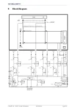
Страница 6: ...GHIELMETTI AG 7UW50 Technische Dokumentation ROR 09 02 2021 Page 6 of 19 9 Block Diagram...

Страница 7: ...GHIELMETTI AG 7UW50 Technische Dokumentation ROR 09 02 2021 Page 7 of 19 10 Control elements of the Tripping Matrix 10 1 Connecting and Diode plugs...

Страница 8: ...GHIELMETTI AG 7UW50 Technische Dokumentation ROR 09 02 2021 Page 8 of 19 11 Interconnecting the Tripping Matrix...

Страница 9: ...GHIELMETTI AG 7UW50 Technische Dokumentation ROR 09 02 2021 Page 9 of 19 11 1 Auxiliary output screw mount connectors...

Страница 10: ...the relay shall be situated in the operating area for at least two hours in order to ensure temperature equalization and to avoid humidity influences and condensation 12 2 Preparations The operating c...

Страница 11: ...t most 0 5s The unit faulty alarm contact of the auxiliary supply circuit must disappear after at most 1s the current consumption data given in the Specifications Open the circuit breaker for the DC p...

Страница 12: ...with the operation of thw protected object as well as the rules and regulations switching earthing etc In order to test the tripping circuits a control command must be given from a protection or super...

Страница 13: ...of 19 During pushing the RESET button the LEDs on the front will light up thus a LED test is performed at the same time The green LED 15V on the front must be on All terminal screws even those not in...

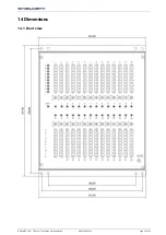
Страница 14: ...GHIELMETTI AG 7UW50 Technische Dokumentation ROR 09 02 2021 Page 14 of 19 14 Dimensions 14 1 Front view...

Страница 15: ...GHIELMETTI AG 7UW50 Technische Dokumentation ROR 09 02 2021 Page 15 of 19 14 2 Back view...

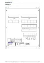
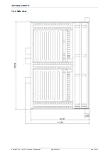
Страница 16: ...GHIELMETTI AG 7UW50 Technische Dokumentation ROR 09 02 2021 Page 16 of 19 14 3 Side view...

Страница 17: ...ity make break 20 VA Switching voltage 250 VAC DC Permission current 0 1 A 250 VDC Matrix Number of columns inputs 2x14 Number of input indication LED 28 Number of rows outputs 10 Number of output ind...

Страница 18: ...ousing cover Warning Hazardous voltages can be present in the device even after disconnection of the supply voltage or after removal of the module from the housing storage capacitors Caution Electrost...

Страница 19: ...9 SWITZERLAND GHIELMETTI AG Head Office Switzerland 41 32 671 13 13 Phone 41 32 671 13 14 Fax info ghielmetti ch www ghielmetti ch GERMANY GHIELMETTI AG Office Germany 49 3371 402 754 Phone 49 3371 61...

Отзывы: