C. Gerhardt GmbH & Co. KG
9
&
$
"
L e v e l - d e t e c t o r
H 2 O
d i s t i l l e d
N a O H
S a m p l e
w a s t e
P o w e r
11
Fig.2.2: Rear view Vapodest 30
DESCRIPTION OF THE SYSTEM
4
5
6
2
3
1
7
8
10
13
12
Страница 1: ...struction manual with care before you start operating the system Please observe the safety instructions of this manual marked with in order to avoid any dangerous handling Vap 30 Order no 7630 e5030 9...
Страница 2: ...w 8 3 Delivery 10 Check for transport damage 10 Parts list 10 4 Assembly and installation 11 Setup 11 Setting into operation 12 5 Programming the system 14 Keyboard 14 Programming the Vapodest 30 17 O...
Страница 3: ...er of electrical shock For repairs on electrical electronic or mechanical parts please al ways contact your agent s service Dont t do repairs by yourself Always switch off the apparatus at the mains a...
Страница 4: ...able parts are excluded from warranty Technical data Voltage 230 V AC 50 Hz Wattage 1600 W Cooling water about 3 litre per distillation minute Cooling wat pressure 1 3 bar Pump capacity Diaphragm pump...
Страница 5: ...4 N C 5 GND 6 VCC 7 N C 8 A driver Out receiver In 9 N C Operating conditions Vapodest distillation systems can be run under normal laboratory conditions For the connection to the tap cold water a fix...
Страница 6: ...with silicone seal 8 PTFE inlet tubing NaOH 9 PP distributor with PP threaded joint 10 Distribution head glass 11 Screw cap GL 32 with silicone seal 12 Distillation condenser 13 Screw cap GL 14 with...
Страница 7: ...KG 7 Fig 2 1 Front view Vapodest 30 DESCRIPTIONOFTHESYSTEM 1 2 3 4 5 6 7 8 9 10 12 11 13 16 17 18 19 20 21 14 15 O n l i n e R e s e t P r o g R u n T i m e S t e p V a p o d e s t S t e a m N a O H H...
Страница 8: ...AN 30 4 Mains cable with appliance plug 5 Excess current switch 10A Cuts off in case of excessive current consumption 6 RS 485 interface 7 Outlet ventilation tubing 8 Excess pressure steam outlet 9 Ex...
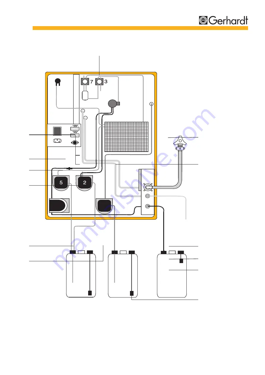
Страница 9: ...C Gerhardt GmbH Co KG 9 L e v e l d e t e c t o r H 2 O d i s t i l l e d N a O H S a m p l e w a s t e P o w e r 11 Fig 2 2 Rear view Vapodest 30 DESCRIPTIONOFTHESYSTEM 4 5 6 2 3 1 7 8 9 10 13 12...
Страница 10: ...obtain an expert s report The exact contents of the delivery can be checked by the follo wing list Parts list Distillation system Vapodest 30 complete Tubing set 1 x Water inlet tube 10 17mm with con...
Страница 11: ...ntroller The Vapodest 30 comes completely preassembled Please un pack the instrument with care 1 Place instrument on work bench 2 Unpack accessories 3 Place set of tanks for distilled water sodium hyd...
Страница 12: ...diode plugs of the level detectors to the distribu tion box and connect to the socket level detection at rear Blank off the remaining diode sockets of the distribution box with the dummy diode plugs e...
Страница 13: ...t is switched on via the mains switch After switching the unit on the pump that fills the steam gene rator starts immediately and the display shows the error mes sage E3 lack of water in the steam gen...
Страница 14: ...0 can be programmed and controlled via the key board of the control panel Entry keyboard Control LED Control keyboard Mains switch Keyboard Fig 5 1 Control panel keyboard Display O n l i n e R e s e t...
Страница 15: ...Prog check memorize and confirm programm Run Start data transfer in synchronous mode on line activated Increasing actual value to desired value Decreasing actual value to desired value Reset Interrup...
Страница 16: ...ing and repeating of program Reset Interruption of program and return to start position On line key pressed Control LED illuminated RS 485 interface is activated Program step H2 O addition Control LED...
Страница 17: ...dest undergoes a pre delivery performance test in the quality assurance department before leaving C Gerhardt On arri val the machine is supplied with the test program If you wish to keep this program...
Страница 18: ...mode or 0 to 99 9 min in minute mode Preset 0 s 4 Distillation time Range 0 to 999 s in second mode or 0 to 99 9 min in minute mode Preset 210 s 4 Power Range 35 to 100 Preset 100 5 Suction Range 0 to...
Страница 19: ...ssistance of the interface a program based on the customers needs can be written too 3 Synchronous working of various equipment The programming and controlling is effected via a system which has been...
Страница 20: ...own on the display Press the Run key to initiate the data transfer from the semi master to the connected instruments After the termination of the data transfer the programming mode automatically ends...
Страница 21: ...fter longer working inter missions holidays etc and each time after the inlet and outlet tubes have been removed 1 Check the chemical tanks 2 Turn on the tap 3 Insert the inlet tube into an empty dige...
Страница 22: ...2 Turn on the tap 3 Insert the inlet tube into an empty digestion tube 4 Lower the quick clamping device and place the digestion tube into position 5 Ensure there is a tight fit between the tube and t...
Страница 23: ...f the tube against the Viton cone 5 Close the protection door and switch the instrument on 6 Enter the program required and start with the key Run 7 Once the program has finished the program remove th...
Страница 24: ...heck the the water inlet steam generator distilled H2 O Filling of the Display shows steam generator last step flashes on stand by Sensor error Switch the water level in system off and steam generator...
Страница 25: ...error Measures Program undefined Check programming Wait for stand by Message dis appears as soon as stand by is reached Excess steam Switch the pressure system off and call service Lack of Check set o...
Страница 26: ...p H2 O sample pos 2 8 Diaphragm pump H2 O steam generator pos 5 9 Silicone tubing 4 7 mm 10 Tubing reduction PP 51x10x5 mm 11 Verprene tubing 8 12 mm 12 Inlet condenser Silicone tubing 8 16 13 Outlet...
Страница 27: ...H Co KG 27 L e v e l d e t e c t o r H 2 O d i s t i l l e d N a O H S a m p l e w a s t e P o w e r MAINTENANCE 17 1 5 6 7 8 19 23 21 25 18 24 Fig 8 1 Tubing diagram 3 2 22 28 26 4 10 11 4 9 14 9 16...
Страница 28: ...604 Silicone seal GL18 16606 Silicone seal GL 32 16607 Plexiglass protection door top 19016 Plexiglass protection door bottom 19015 New plexiglas protection door single 19017 Door handle brown 18251 D...
Страница 29: ...12 mm 2 m 22604 PVC pipe 6x1 mm 400 mm 25450 PVC pipe 10x1 mm 400 mm 25451 Set of tanks KAN 30 3 pieces with 7639 float switch RS 232 485 ARS 4260 Data cable DK 42 for RS 485 2 m 4261 Data cable DK 4...
Страница 30: ...time 420 s Steam capacity 100 Suction time 20 s or 0 s It is recommended that the NaOH line is flushed daily so that no NaOH is left in the chemical lines overnight Place an empty digestion tube and...
Страница 31: ...C Gerhardt GmbH Co KG 31...