


22
Section 4: System Operation
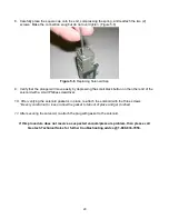
Establishing the Product Recovery Cycle Time
The first thing to consider will be a product recovery rate target. The maximum product amount that can
be recovered is determined by the recharge rate of each individual well. You can size and adjust your
system for optimal recovery rate potential based on the parameters obtained from the well.
The best measure of success is the average measured recovery of fluid in the recovery tank, over a
specific time frame, compared to the recovery rate target. Due to seasonal and weather related
variability in available solar energy it may be very difficult to schedule site visits to coincide with the
system pumping product. If observation of the system in action is desired, schedule a visit in the mid
afternoon. Otherwise, record your cycle counter value and total run time and compare these with the
amount of product recovered.
The vacuum cycle pulls the product into the pump housing. The system compressor will then switch to
pressure mode. The compressor is capable of providing up to 100 PSIG (7 bar) (pressure to the pump
and the discharge line). The pressure cycle pushes the intake valve shut and forces the product past
the discharge valve and up the discharge line to the surface.
It is important that you verify that all product is being pushed out of the pump housing before the next
vacuum cycle begins. If the vacuum time interval is set too long, or the pressure cycle set for too short
of a period, it is possible for the pump to overfill and for the product to be pulled up the air line and into
the Intake Float Switch. If this happens, set the vacuum time back to 0 seconds and the pressure to 30
seconds and evacuate all the fluid from the float switch housing. After the system is clear of excess
fluid, try setting the vacuum time to a lower setting and increase your pressure time to a higher setting
for better operation.
It’s better to start with a higher pressure and lower vacuum setting and adjust over
time.
The standard stainless steel pump is capable of holding 0.2 gallons (0.750 mL) of fluid per cycle. That
translates into over 14
” (35 cm) of product layer in a 2” (5 cm) well and about 3.5” (8.9 cm) of product
layer in a
4” (10 cm) well. This represents the minimum product layer thickness required to achieve one
full pump housing of product per cycle. Even if there is that much product in the well, it is not advisable
to pump the product layer all the way down. See Recovery Rates in
Section 1: System Description
for
further explanation.
If Sipper system is to be deployed in humid conditions, it is recommended to install
the optional Desiccant Dryer to prevent frequent solenoid maintenance. See
Section
9: Parts and Accessories
for part information.
Содержание Solar Sipper
Страница 1: ...Rev 10 12 2017 Part 16550176 Geotech Sipper Installation and Operation Manual...
Страница 2: ...i...
Страница 16: ...13 Figure 2 5 Example of Tankfull Probe...
Страница 23: ...20 Figure 3 1 Flowchart of User Interface Label...
Страница 24: ...21 Figure 3 2 Example of Solar Sipper front panel...
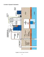
Страница 38: ...35 Section 8 System Schematics Figure 8 1 Solar Sipper Schematic...
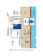
Страница 39: ...36 Figure 8 2 AC Sipper Schematic shown with optional Desiccant Dryers...
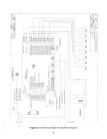
Страница 40: ...37 Figure 8 3 8 Well Solar Sipper Internal Wiring Diagram...
Страница 41: ...38 Figure 8 4 3 Well Solar Sipper Internal Wiring Diagram...
Страница 45: ...42 Notes...


