14
5.3.2.
Simplified Two-layered Earth Interpretation
In general, a two-layered earth has three unknown quantities,
1
,
2
, and t, whereas
measurements made with the EM38-MK2 on the ground produce only two measured quantities,
av
(the apparent conductivity in the vertical dipole mode) and
ah
(the apparent conductivity in
the horizontal dipole mode). If one of the two unknown conductivities is much greater than the
other and we may assume that the smaller conductivity is zero we are left with only two
unknowns and the problem is fully resolved. If
1
>>
2
we obtain the conductivity and the
thickness of the upper (conductive) layer; if
2
>>
1
we obtain the depth to and the conductivity
of the lower (conductive) layer.
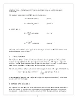
Given
ah
and
av
the procedure is as follows: if
av
>
ah
calculate the ratio
ah
/
av
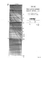
and with
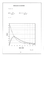
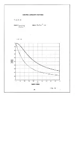
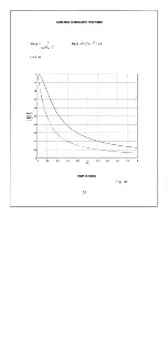
this ratio use curve (1) Fig. 7 to determine z, the depth to the conductive substrate. Given z, use
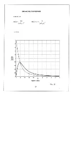
Fig. 3 to obtain either R
h
(z) or R
v
(z) whence
σ
2
σ
ah
R
h
(
z
)
σ
av
R
v
(
z
)
and the problem is solved.
If on the other hand
ah
>
av
, calculate
av
/
ah
and with this ratio use curve (2) in Fig. 7 to
determine z, the thickness of the conductive upper layer. Given z use Fig. 3 to obtain either
R
h
(z) or R
v
(z) whence
σ
1
σ
ah
1
R
h
(
z
)
σ
av
1
R
v
(
z
)
Note that in the event that neither
1
>>
2
or
2
>>
1
it is still possible to use this procedure to
define an apparent conductivity and an apparent thickness (or depth) which should be reasonably
valid as long as a reasonable conductivity contrast exists. If the earth has more than two layers
this procedure defines the equivalent two layered earth.
6. MEASURING SOIL MAGNETIC SUSCEPTIBILITY
It is a simple matter to measure the magnetic susceptibility of the upper half meter of the soil
using the EM38-MK2 in the vertical dipole mode. Set the Mode switch to the I/P position so
that the instrument is measuring the inphase component from the ground and lift the instrument
to a height of approximately 1.5 meters above the ground. Set the meter reading to
approximately 50 mS/m using the I/P zero controls and note the apparent conductivity reading at
this height. With the Mode switch still in the I/P position, lower the instrument to the surface
and again measure the apparent conductivity. It will be observed that as the instrument is
lowered, the meter reading initially swings to lower conductivity, then returns to the conductivity
Содержание EM38-MK2
Страница 7: ...5 Fig A...
Страница 23: ......
Страница 24: ......
Страница 25: ......
Страница 26: ......
Страница 27: ......
Страница 28: ......
Страница 29: ......
Страница 30: ......
Страница 31: ......
Страница 32: ......
Страница 33: ......
Страница 34: ......
Страница 35: ......
Страница 36: ...34...
Страница 37: ...35...
Страница 38: ...36...
Страница 39: ...37...
Страница 44: ...42...


