background image

30 


Save Stored Data:

 Saves all stored data (from the current session) for the selected 

sensor. A message is displayed informing the user how many readings were stored. The 
“Readings Stored:” counter will also be reset to “0”. The readings are saved to a file 
contained in a special data folder under the sensor configuration folder structure. The 
readings are either saved to a new data file or appended to an existing data file. Please 
refer to the “Storage Configuration” section below for more information. 


Store Zero Reading Value:

 This feature allows the currently displayed reading to be 

used and the sensor configuration’s “Zero Reading” value. When this menu item is 
tapped, a snapshot of the current reading is taken and converted to digits. Before storing 
this raw value in the sensor configuration, a confirmation dialog is displayed giving the 
user the opportunity to see the value before continuing. 


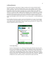
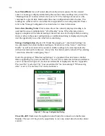
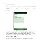
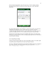
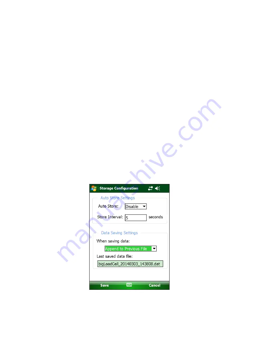
Storage Configuration (

Figure 47

):

 Under the grouping of “Auto Store Settings” are 

two parameters that allow multiple readings to be taken over time. Select “Auto Store: 
Enable” as well as an interval in seconds to enable readings to be stored periodically 
without intervention from the user. At any time this feature can be turned off by selecting 
“Auto Store: Disable” and tapping “Save”. 


Under the grouping of “Data Saving Settings” is a parameter that determines whether 
data is appending to a previous data file or if a new file is created each time stored data is 
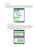
saved. As shown in Figure 47, the last saved data file is displayed when the “Append to 
Previous File” is selected. The “Last saved data file” has no meaning if “When saving 
data:” is set to “Create New File” and is not shown. 


Figure 47 - Storage Configuration Dialog 


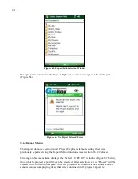
Close GK-405:

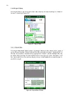
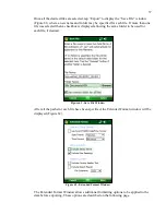
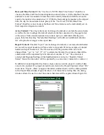
 Shuts down the application and breaks the connection to the Remote 

Module. The user will be given the opportunity to save any stored data (from the current 
session). 


Содержание GK-405

Страница 1: ...thout the written consent of Geokon Inc The information contained herein is believed to be accurate and reliable However Geokon Inc assumes no responsibility for errors omissions or misinterpretation The information herein is subject to change without notification Copyright 2013 2018 by Geokon Inc Doc Rev I 05 03 2018 ...

Страница 2: ......

Страница 3: ...re are no warranties except as stated herein There are no other warranties expressed or implied including but not limited to the implied warranties of merchantability and of fitness for a particular purpose Geokon Inc is not responsible for any damages or losses caused to other equipment whether direct indirect incidental special or consequential which the purchaser may experience as a result of t...

Страница 4: ......

Страница 5: ...enu 23 3 5 APPLICATION MENU 26 3 5 1 Live Readings With Selected Sensor 27 3 5 2 Edit Settings 32 3 5 3 Remote Connect with 32 3 5 4 Terminal Window 34 3 5 5 About GK 405 VWRA 34 3 6 FILE MENU 35 3 6 1 Delete Data Files 35 3 6 2 Export Menu 36 3 6 3 Import Menu 40 3 6 4 View Data 41 3 6 5 Close GK 405 42 4 CONFIGURING PROJECT EXPLORER ELEMENTS 43 4 1 PROJECT CONFIGURATION 43 4 2 SENSOR CONFIGURATI...

Страница 6: ...o a Load Cell with Flying Leads 60 A 3 CHARGER CONNECTIONS 61 APPENDIX B CHANGING A FUSE 62 APPENDIX C REMOTE MODULE COMMAND STRUCTURE 64 APPENDIX D DATA FILE FORMATS 66 D 1 RAW DATA TEXT REPORT 66 D 2 DATA TEXT REPORT WITH COLUMN AND REPORT HEADERS 67 APPENDIX E SPECIFICATIONS 68 E 1 GK 405 REMOTE MODULE SPECIFICATIONS 68 E 2 HANDHELD DEVICE FPC 2 SPECIFICATIONS 69 ...

Страница 7: ...URE 24 SELECT WORKSPACE NAME 16 FIGURE 25 WORKSPACE FOLDER SELECTION 17 FIGURE 26 WORKSPACE EXIST 17 FIGURE 27 REMOTE MODULE NOT FOUND 18 FIGURE 28 DEFAULT INITIAL SCREEN 18 FIGURE 29 LIVE READINGS RAW READINGS 19 FIGURE 30 DISPLAY MODE DROPDOWN MENU 20 FIGURE 31 SENSOR INDEX DROPDOWN CONTROL 21 FIGURE 32 MENU OPTIONS 21 FIGURE 33 VIEW OPTIONS 21 FIGURE 34 SENSOR SELECTION SCREEN 22 FIGURE 35 PROJ...

Страница 8: ...74 LINEAR COEFFICIENTS 46 FIGURE 75 POLYNOMIAL COEFFICIENTS 47 FIGURE 76 UNITS CONVERSION 48 FIGURE 77 SENSOR SETTINGS PAGE 4 NAUTIZ X8 SHOWN 49 FIGURE 78 NONSTANDARD THERMISTOR COEFFICIENTS 50 FIGURE 79 CANNOT CONNECT ERROR MESSAGE NAUTIZ X8 SHOWN 53 FIGURE 80 BLUETOOTH DEVICE CONTEXT MENU 54 FIGURE 81 CONNECTION PROBLEM ERROR NAUTIZ X8 SHOWN 55 FIGURE 82 BLUETOOTH SETTINGS WINDOW COM PORTS TAB 5...

Страница 9: ...e measured Figure 1 GK 405 with Handheld PC in Cradle Shown with the FPC 2 The two components communicate wirelessly using Bluetooth a reliable digital communications protocol The Readout Unit can operate from the cradle of the Remote Module as shown in Figure 1 or if more convenient can be removed and operated up to 20 meters from the Remote Module Note In most cases 20 meters will be the maximum...

Страница 10: ...eight and simple Remote Module Lithium battery 8 hours of continuous use One button operation automatic power down when Bluetooth connection is dropped or after several minutes of inactivity Reliable connection to standard vibrating wire gages and load cells is accomplished via two 10 pin bulkhead connectors see Figure 2 Housed in a durable aluminum enclosure Figure 2 Vibrating Wire Gage and Load ...

Страница 11: ...les connected to vibrating wire gages Figure 3 Handheld PC FPC 2 Running GK 405 VWRA 1 4 Before using the GK 405 Vibrating Wire Readout The readout software runs as an application under Windows Mobile 5 or 6 operating system installed on a handheld PC Please familiarize yourself with the handheld PC and the Windows Mobile OS It is assumed in the instructions below that you can launch applications ...

Страница 12: ...2 2 through 2 4 can possibly be skipped but a quick review is recommended 2 1 Connecting Sensors 2 1 1 Sensors with 10 pin Connectors Attached Align the grooves on the sensor connector male with the appropriate connector on the readout female connector labeled senor or load cell Push the connector into place and then twist the outer ring of the male connector until it locks into place For more inf...

Страница 13: ...g Wire Readout the first time If the Live Readings Window is displayed but no Thermistor or Vibrating Wire output is shown please refer to Appendix A GK 405 Connections Figure 5 Select Workspace Name 3 From the Live Readings Window different display modes may be selected as appropriate for the sensor see Section 3 2 1 Display Mode If a sensor is connected that contains more than one vibrating wire...

Страница 14: ...oth Settings Manager on the handheld PC to set up the link to the remote Read about setting up a Bluetooth partnership in Chapter 9 of the handheld PC s Reference Guide See Figure 6 below for two examples of how to start Bluetooth Manager Figure 6 Starting Bluetooth Manager 2 Once in the Bluetooth Settings Manager click on the Mode tab and then make sure that the box next to Turn on Bluetooth is c...

Страница 15: ...ntain the remote s serial number go to step six Otherwise turn on the remote module should see a flashing blue indicator on the remote and select Add new device Figure 8 Add New Device 4 When a suitable remote is discovered highlight the device and tap Next Figure 9 Select a Bluetooth Device ...

Страница 16: ...he prompt shown at the bottom of Figure 10 and then return to the Bluetooth Devices screen Figure 10 Enter Passcode 6 Click on the COM Ports tab if the Geokon device is already assigned to a COM Port skip to step nine If no COM Port is assigned tap on New Outgoing Port In the example shown in Figure 11 there is no COM Port assigned to a GK405 device Figure 11 New Outgoing Port ...

Страница 17: ... COM5 is the default Be sure to remember the number of the COM port as you may have to select it later in the readout software see Section 3 5 3 Make sure to uncheck the Secure Connection checkbox Figure 13 Tap Finish when done to return to the Bluetooth Settings COM Ports screen Note If using a Nautiz X7 COM5 may be available depending on the model Figure 13 COM Port Selection ...

Страница 18: ...ox is checked Tap Save to complete the Bluetooth Settings Figure 14 Serial Port Check Box NOTE After Save is selected you will be brought back to the Devices window There will be a Connect button available at the bottom of the screen See Figure 15 below DO NOT USE THE CONNECT BUTTON TO TEST THE CONNECTION It will always fail after the pairing has been made successfully Test the pairing by entering...

Страница 19: ... the HHD must be established either via a physical link or Bluetooth Note For customers using a PC running Window 10 operating system Windows Mobile Device Center WMDC may no longer operate as it should because of an operating system update released October of 2017 called Fall Creator Update If WMDC no longer launches when a mobile device is connected via USB cable or will not manually launch the ...

Страница 20: ...12 Figure 17 Windows Mobile Device Center ...

Страница 21: ...e the contents of your device to call up an Explorer Window for the HHD see Figure 18 The procedure for ActiveSync is very similar Figure 18 Windows Explorer Window Displaying HHD Root Folder 2 In the Explorer Window double click the icon labeled to navigate to the handheld PC s system root shown in Figure 19 Figure 19 Handheld Device Root Folder Contents ...

Страница 22: ...installation folder Figure 20 Figure 20 Installation Folder Contents 4 Copy the file GK405_Installer CAB from the installer folder to the HHD system root folder From the HDD navigate to the system root folder using File Explorer Figure 21 and tap the file GK405_Installer to execute the installer Figure 21 GK 405 Installer at Root of HDD ...

Страница 23: ...Device be selected then tap Install with the stylus to initiate the install process Figure 22 GK 405 Install Screen 6 The file GK405_Installer CAB can be now deleted from the system root folder to free up memory The GK 405 VW Readout application is now installed and its icon should appear in Start Programs Figure 23 Figure 23 GK 405 VWRA Icon in Start Programs ...

Страница 24: ...r handheld device where all the workspace elements will be stored Figure 25 As can be seen below the default workspace location is in a folder name the same as the workspace name under a special shared folder reserved for workspaces For Windows Mobile devices this folder is located at Application Data Geokon GK 405 Workspaces GK 405 VWRA appends the name of the new workspace to this shared folder ...

Страница 25: ...me Figure 26 Figure 26 Workspace Exists After the initial workspace is created the GK 405 VWRA will attempt to connect to a remote module If no remote module can be found then the error message shown in Figure 27 will be displayed By default the GK 405 VWRA looks for a remote module connection on COM5 but will remember the COM number of the last successful connection Please see Section 2 3 for mor...

Страница 26: ...ject s and add new sensor configurations to your workspace Figure 28 Figure 28 Default Initial Screen Note With all subsequent attempts to connect to the Remote Module please ensure that the Power On button on the Remote Module has been pressed blue light will be blinking before launching the GK 405 VWRA Figure 27 Remote Module Not Found ...

Страница 27: ... usually digits since no sensor has been selected to supply parameters for engineering unit display The following sections describe the GK 405 VWRA user interface in detail 3 2 Live Readings Screen Raw Readings Figure 29 shows a typical vibrating wire piezometer output in digits and thermistor output in degrees Celsius Figure 29 Live Readings Raw Readings In Raw Readings mode the two onscreen cont...

Страница 28: ...etermine the best choice for the sensor to be measured Figure 30 Display Mode Dropdown Menu Display Mode Geokon Model Calculation Units Sweep Freq hz A All Period T Microseconds 450 6000 B 4300BX 4400 4500 4600 4700 4800 4900 F2 x 10 3 1 Digits 1400 3500 C 4000 F2x10 3x4 062 Microstrain 450 1200 D 4200 F2x10 3x3 304 Microstrain 450 1200 E 4100 F2x10 3x0 39102 Microstrain 1400 3500 F 4300EX F2 x 10...

Страница 29: ... Figure 31 Sensor Index Dropdown Control In addition to the controls described in Sections 3 2 1 and 3 2 2 Menu Options Figure 32 and View Options Figure 33 allow functionality such as storing saving and viewing data In Raw Readings mode the only Menu Option enabled is Close GK 405 while valid View Option choices are Sensor Selection Screen described further in Section 3 3 and Landscape Mode Lands...

Страница 30: ...ropdown menu See Section 3 4 Application Menu Allows display changes workspace project and sensor configuration as well as connection to the remote module See Section 3 5 File Menu File and project explorer element exporting and importing Data file viewing and deleting options See Section 3 6 Status Area Displays the connection status of the application Table 2 Sensor Selection Components Note Whi...

Страница 31: ...icking on the sign preceding project name In the hierarchy of the project explorer sensors are child elements of a project Sensor settings can be edited by selecting the desired sensor in the explorer tree Once selected sensor settings can be displayed using Edit Settings from the context menu see Section 3 4 1 5 below or by using the Application Menu see Section 3 5 Figure 35 Project Explorer wit...

Страница 32: ...this menu item to display the Workspace Selection window Figure 37 Click on the dropdown control to display the available workspaces Figure 38 Figure 38 List of Workspace Names Alternatively a new name can be entered in the workspace name selection box If the GK 405 VWRA recognizes the name as a workspace it has opened before it will reopen the existing workspace Figure 37 Workspace Selection Wind...

Страница 33: ...u item will only be enabled when the workspace is selected 3 4 1 3 Add Sensor This menu item allows new sensor configurations to be created and added to a project After tapping on this Context Menu item the Sensor Settings Dialog will be displayed and can be edited See Section 4 2 for more information regarding sensor configuration This menu item will only be enabled when a project is selected 3 4...

Страница 34: ...nts sub item Figure 40 Figure 40 Sort Elements Sub Items 3 5 Application Menu The GK 405 VWRA Application Menu provides access to the high level application functionality It is located in the lower right corner of the main window frame Figure 41 The Edit Settings menu item can also be accessed via the context menu Figure 41 Application Menu ...

Страница 35: ...ected at the bottom of the main screen Both of the connection indicators are shown inside red ovals in Figure 42 see Section 2 3 and 3 5 3 for information regarding connecting to the remote module Figure 42 Sensor Selection Screen Remote Module Connected Tapping on the Live Readings menu item displays the sub menu shown in Figure 43 Tap on With Selected Sensor For information on the Raw Readings o...

Страница 36: ...or Display mode the default when entering this window which cause the raw sensor output to be converted to engineering units See Section 4 2 Sensor Configuration for more information on engineering units Note that when a sensor is selected Live Readings contains a Store button shown on the right that allows multiple readings to be stored for a particular sensor With each tap on this button a new r...

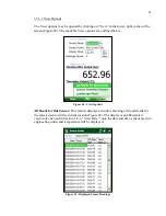
Страница 37: ... Figure 45 Menu Options Clear Data Allows clearing of all readings stored in the current session for the selected sensor Tapping this menu option displays the warning shown in Figure 46 Tapping Yes will clear all data from the current session and will reset the Readings Stored counter to 0 This feature has no effect on previously saved data Figure 46 Clear Data Warning ...

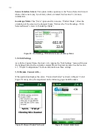
Страница 38: ...user the opportunity to see the value before continuing Storage Configuration Figure 47 Under the grouping of Auto Store Settings are two parameters that allow multiple readings to be taken over time Select Auto Store Enable as well as an interval in seconds to enable readings to be stored periodically without intervention from the user At any time this feature can be turned off by selecting Auto ...

Страница 39: ...low Figure 48 View Options All Reads for this Sensor This feature displays a window showing all stored reads for the selected sensor in the current session Figure 49 The display is an abbreviated version of one used in Section 3 6 4 View Data only the date and time sensor read in engineering units and temperature will be displayed Figure 49 Displayed Sensor Readings ...

Страница 40: ...de Figure 50 Live Readings With Selected Sensor Landscape Mode 3 5 2 Edit Settings As with the Context Menu Section 3 4 1 tapping the Edit Settings menu will invoke the Settings Editor for the currently selected Project Explorer element See the Section 4 1 Project Configurations for more information on these settings 3 5 3 Remote Connect with If the application displays the status Connection Faile...

Страница 41: ...nnect with Figure 53 and pick the COM port previously established in Section 2 3 Figure 54 Figure 54 Select COM Port A successful connection is reflected in the Main Screen status as shown by the red ovals in Figure 55 Figure 55 Sensor Selection Screen Remote Module Connected Figure 53 Remote Connect With ...

Страница 42: ...dule See Appendix C for more information regarding the Remote Module command structure Figure 56 Terminal Window After typing a command in the Command text box tap the Send menu to issue the command to the Remote Module Repeated taps of Send will reissue the same command Typing a command in the Command text box followed by a keyboard Enter will cause the Remote Module to execute the command one ti...

Страница 43: ...r data files Figure 57 File Menu Options 3 6 1 Delete Data Files If a sensor is selected and contains data files then tapping on the Delete Data Files File Menu option displays the window shown in Figure 58 Select one or more individual files or use the Select All Files checkbox to select all files Tapping on Select will cause the GK 405 VWRA to prompt the user to confirm that they really want to ...

Страница 44: ...a from the current sensor selected via the Project Explorer Figure 60 shows the files available for sensor bigLoadCell A file may be selected or deselected by tapping in the Select column Multiple files may be selected for exporting If a selected file name is too long to fit in the File Name text box tap inside the text box and use the arrow keys on the handheld s external keypad to scroll left or...

Страница 45: ...box is displayed allowing the same folder to be used for each file if desired Figure 61 Save File Window After all the paths for each file have been specified the Extended Format window will be displayed Figure 62 Figure 62 Extended Format Window The Extended Format Window allows additional formatting options to be applied to the data before exporting These options are described on the following p...

Страница 46: ...s the average to the export data Report Content The data report can be changed to include or exclude column header text as well as report header text Please refer to Appendix D for an example of column header and report header text The file extension for the generated file can also be changed from csv to txt If txt is selected as the data file extension then all the column data will be separated b...

Страница 47: ...is possible and multiple data files will be formatted and exported to the export folder Tapping Next again displays the same Extended Format dialog as for single sensor data export See Figure 62 above and the accompanying description for more information about Extended Formatting 3 6 2 2 Export Project Settings Clicking on this menu item displays the Select Export Path window from which a path to ...

Страница 48: ...rer element settings that were previously exported using the Export Menu functions see Section 3 6 2 2 above Clicking on this menu item displays the Select LVPE File window Figure 67 below from which a project export file can be selected After selection a new Project will be created in the current workspace This new project will contain all the settings and any sensors and accompanying data that w...

Страница 49: ... the project import will be cancelled 3 6 4 View Data When the View Data Menu is clicked and a sensor has been previously selected the Select File to View window is displayed Figure 68 shows the files available for sensor bigLoadCell A file may be selected for viewing or deselected by tapping in the Select column Figure 68 Data File Selection Window ...

Страница 50: ...bottom of the screen can be used to display columns that are currently out of view Figure 69 Sensor Reads Window 3 6 5 Close GK 405 Tapping on this menu item will cause the program to cease execution This behavior is the same as tapping on ok in the upper right corner of the display screen ...

Страница 51: ...t Configuration Figure 70 depicts the Projects Settings window The fields in the Project Settings window are described below Figure 70 Project Settings Project ID Read only value generated when the project was created Used internally by the GK 405 VWRA Project Name Use the onscreen keyboard to enter a unique and descriptive name for the project Description Using the onscreen keyboard enter a brief...

Страница 52: ... Window Sensor name This is a user assigned sensor name which is displayed in the project explorer A descriptive name allows the user to quickly pick the sensor from the list Description Verbose description of the sensor which can provide clues to its location purpose etc Sensor ID This is a system generated sensor ID assigned at the time of sensor configuration creation This value uniquely identi...

Страница 53: ... Figure 72 Sensor Model 49xx Selected 4 2 2 Sensor Settings Page Two Conversion Method and Coefficients The second page of the Sensor Setting window contains parameters that determine how sensors are converted from Digits to Engineering Units The upper portion of the screen contains radio buttons to select either the Linear or Polynomial conversion method Figure 73 Each conversion method and the c...

Страница 54: ...d selections are G R0 R1 G R1 R0 and Digits Only When this parameter is set to Digits Only as shown in Figure 74 no gage factor needs to be entered The GK 405 VWRA will display raw digits readings See Section 3 2 for information on raw readings Please consult the calibration sheet for each sensor to determine which formula G R0 R1 or G R1 R0 to select for the setting above Zero Reading This parame...

Страница 55: ...et for this parameter Coefficient B Enter the Polynomial Gage Factor B from the Sensor Calibration Sheet for this parameter Coefficient C This parameter should be calculated from a field zero reading Please refer to your transducer manual for further details on how to calculate Coefficient C 4 2 3 Sensor Settings Page Three Units Conversion The third page of the Sensor Setting window see Figure 76...

Страница 56: ...its that are different from those specified on the calibration sheet may have unexpected consequences Output units Engineering units of values read and or logged by the GK 405 The choices for this parameter are dependent on the Measurement and Input units selected above and can be metric or English units Conversion Factor This parameter is dependent on Measurement Input units and Output units sele...

Страница 57: ... feature does not apply to all sensors and will be disabled grayed out when the following sensor models are selected 4200 4202 4204 421X 44xx and 49XX Sensor Correction The choices for this parameter are Enabled or Disabled Select Enable to enable correction of any errors in the sensor reading due to temperature Initial Temperature Initial temperature reading taken when performing a Zero Reading o...

Страница 58: ... is always enabled to allow temperature units to be selected Thermistor Type Allows selection of the Thermistor type Valid selections are Standard High Temp 8 2K High Temp 10K or Other The first three are Geokon thermistor offerings based on the type of sensor purchased Selecting the Other choice causes four more text boxes to be displayed Figure 78 where up to four thermistor coefficients may be ...

Страница 59: ...nded Connecting the Field PC to a desktop or laptop PC using the supplied USB cable Type A to mini B is straight forward and allows the user to view the Field PC s storage as a flash drive on the desktop laptop you can then drag the files around to any folder on the desktop laptop If you are using Windows XP you will need to download and install the program ActiveSync This application is available...

Страница 60: ...u After exporting the resulting lvpe file should be transferred to a desktop PC using the techniques described in Section 5 1 Although backing up a project automatically includes any data files stored as part of the project element sensor structure data files can be individually backed up per hole using the Data Export function from the File menu After exporting the resulting csv file should be tr...

Страница 61: ...ect Your device did not connect with GK405SNxxxxxxxxx The connection failed or the passcode is incorrect Figure 79 Cannot Connect Error Message Nautiz X8 Shown The message shown in Figure 79 is most commonly caused by tapping the Connect menu item from Bluetooth Device Context Menu see Figure 80 on the following page after a successful pairing has been established If the Connect menu item has been...

Страница 62: ...54 Figure 80 Bluetooth Device Context Menu This connection method will never be successful and should not be used to test the pairing To test the pairing use the GK 405 VWRA as outlined in Section 3 5 3 ...

Страница 63: ... used by the GK 405 by checking in the COM Port section of the Windows Bluetooth settings see Figure 82 on the following page Select that COM Port from the GK 405 application s COM sub menu of the Remote Connect with menu Figure 83 then tap to reconnect See Section 3 5 3 for more information If the connection attempt fails multiple times when the verified COM port is selected perform a full power ...

Страница 64: ...56 Figure 82 Bluetooth Settings Window COM Ports Tab Figure 83 Remote Connect With ...

Страница 65: ...ule Attach Remote Module charger for two hours then try again After tapping on the Live Readings the blue light never goes solid blue and a Communications error screen is displayed Check the Bluetooth status on the FPC 2 and ensure Bluetooth is On Check that there is a valid Bluetooth pairing in the Bluetooth Setting window of the FPC 2 Refer to Section 2 3 The GK 405 appears to be hung or frozen ...

Страница 66: ...or connector Table 4 lists the pinout for this connector Figure 84 Single Sensor Connector 10 pin Bulkhead PT06F 12 10P Alligator Clip Boot Color Flying Leads Signal Description A Red Vibrating Wire Gage B Black Vibrating Wire Gage C White Thermistor D Green Thermistor E Blue Shield F G H J K Table 4 Single Sensor Pin out ...

Страница 67: ...connector Figure 85 Load Cell Connector 10 pin Bulkhead PT06F 12 10P Signal Description A Vibrating Wire Gage 1 B Vibrating Wire Gage 2 C Vibrating Wire Gage 3 D Vibrating Wire Gage 4 E Vibrating Wire Gage 5 F Vibrating Wire Gage 6 G Shield Common H Vibrating Wire Gage Common J Thermistor K Thermistor Table 5 Load Cell Connector Pin out ...

Страница 68: ... in the wiring diagram in Table 6 Each sensor is read in turn by clipping either the red or black clip to the lead marked common and the black or red clip in turn to the leads marked 1 2 3 etc The blue clip should be connected to the cable shield and the green and white clips to the cable leads marked thermistor 10 pin Bulkhead PT06A 12 10P Function 3 Gage VW Load Cell Geokon Purple Cable 4 Gage V...

Страница 69: ... To charge the remote module plug the CHG 04 into the charger port shown in Figure 86 The CHG 04 has an LED indicator which indicates red when the unit is charging and green when it is fully charged Figure 86 Charger Connection ...

Страница 70: ...ANGING A FUSE 1 Remove the eight Philips head screws that hold the faceplate of the remote module in place 2 Remove the faceplate by gently pulling on the readout unit cradle Figure 87 Figure 87 Removing the Face Plate ...

Страница 71: ...in place and flat against the internal flange 6 Carefully place the faceplate back into the remote module taking care not to pinch the exterior rubber gasket while doing so 7 Reinstall the eight seal screws into the faceplate Make sure the seal rings on the underside of the screws seal against the faceplate Do not over tighten the seal screws this can deform the black overlay on top of the facepla...

Страница 72: ...T Table 7 Remote Module Command Format Example 1 READ FIRMWARE VERSION Reads the firmware version of the Remote Module Command 4 CR Response Geokon405 Ver1 0 0320 Example 2 REQUEST 6 READS Get sensor readings for up to six Vibrating Wire cells 0000000 returned for unconnected gages Command V6 CR Response 0200000 0000000 0000000 0000000 0000000 0000000 Notes The above response shows that there is o...

Страница 73: ...ECTRUM Set the operating pluck spectrum to the B range 1400 3500 Hz for each gage Command V6B CR Response BBBBBB Example 4 TAKE BATTERY READING Display the current voltage level of the lithium battery Command V7 CR Response 7 6 ...

Страница 74: ...ated columns above represent the following Column 1 represents the year when the array was stored Column 2 represents the Julian day when the array was stored Column 3 represents the hour when the array was stored Column 4 represents the minute when the array was stored Column 5 represents the second when the array was stored Column 6 represents the vibrating wire reading in engineering unit if ap...

Страница 75: ...es additional report formatting capability by adding column and report headers shown in Excel format for clarity Note that the sensor name has also been included and the date and time appear as one field by using the Y1900 Date Time option Figure 89 Enhanced Data Text Report ...

Страница 76: ...ge 50 to 150 Celsius Measurement Resolution 0 1 Celsius Measurement Accuracy 0 5 to 1 0 FSR Communications Wireless protocol Bluetooth 2 0 EDR Class 1 range 20 m Bluetooth profile Serial Port Profile SPP Parameters 9600 baud eight data bits one stop bit no parity full duplex non configurable Transmission Format ASCII Physical Dimensions L W H 210 mm 165 mm 185 mm 8 25 6 5 7 25 Weight 2 45 kg 5 40 ...

Страница 77: ...nnections USB A Host USB micro PC sync and charging DB9 RS 232 serial 3 5 mm headset stereo and mic Case IP67 waterproof Camera 8 megapixel rear facing with autofocus and LED illumination Environmental Tested to MIL STD810G for water humidity sand dust vibration altitude shock and temperature Power Battery Life Charge Time 5200 mAh 3 7 V Li Ion warm swappable battery approx 8 5 hours approx five h...

Отзывы: