28
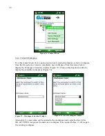
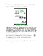
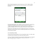
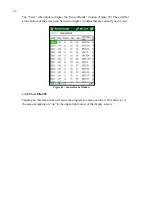
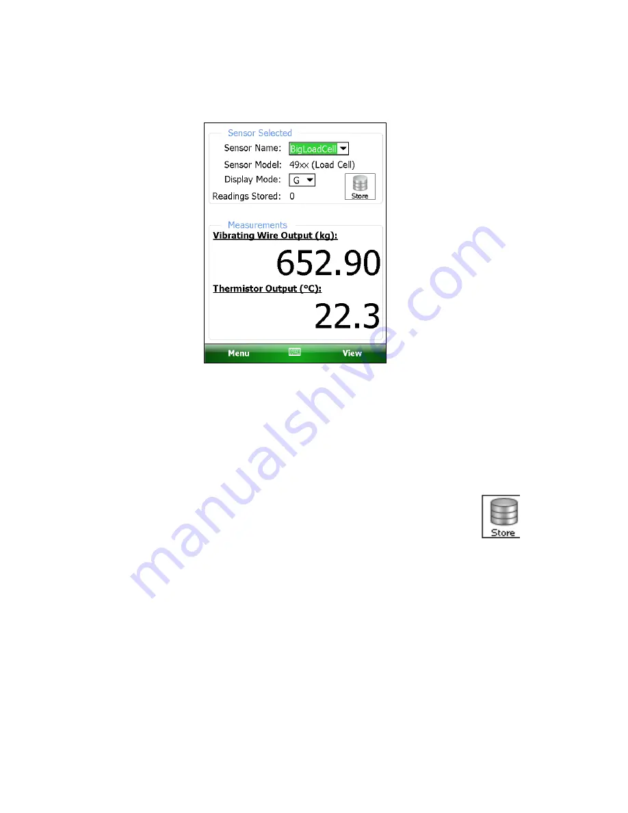
Tapping this menu item will cause the Live Readings screen to be displayed with its
parameters initialized for the specific sensor selected (Figure 44). Please refer to
Appendix A for information regarding sensor connections.
Figure 44 - Live Readings Screen (Sensor Selected)
Much like in “Live Readings – Raw Readings” (See Section 3.2), Display Mode contains
selections “A – F”, corresponding to different sensor “pluck” frequencies (see Table 1).
The “Live Readings - With Selected Sensor” window also contains a “G” selection for
Display mode (the default when entering this window) which cause the raw sensor output
to be converted to engineering units. (See Section 4.2, “Sensor Configuration”, for more
information on engineering units.)
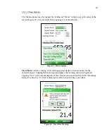
Note that when a sensor is selected, Live Readings contains a “Store”
button (shown on the right) that allows multiple readings to be stored for a
particular sensor. With each tap on this button, a new reading is stored for
the selected sensor. Each time a reading is stored, a “beep” will be heard
from the handheld unit.
A different sensor can be selected for measurement by accessing the dropdown box to the
right of the “Sensor Name:” label. The new sensor can be chosen from the list of all
sensors in the project.
Содержание GK-405
Страница 2: ......
Страница 4: ......
Страница 20: ...12 Figure 17 Windows Mobile Device Center ...
Страница 64: ...56 Figure 82 Bluetooth Settings Window COM Ports Tab Figure 83 Remote Connect With ...

