background image


A 12V – 7Ah lead acid battery is used to provide power for the Datalogger. The battery supports 

operating power for a limited period of time should the AC or solar power, used to maintain the 

battery, be interrupted. Under normal operating conditions and proper maintenance, the life 

expectancy of the battery is approximately five years 


3.1 Installation 


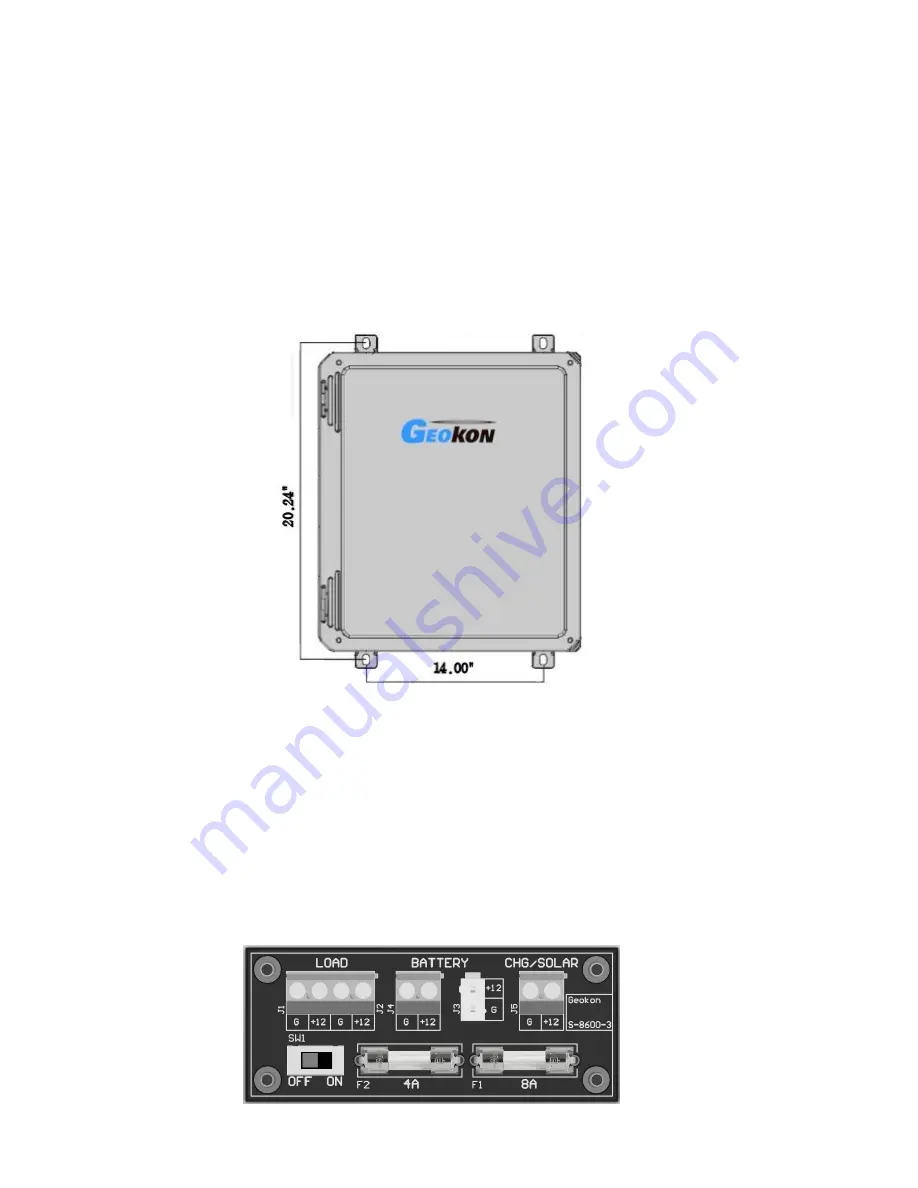
The recommended method of installation involves attaching the various enclosures (MICRO-

6000 and Multiplexers) to a fixed structure, such as a wall, in an upright position (Figure 1). 

Mounting dimensions shown in inches. 


Figure 1 - Typical Micro-6000 Configuration 


3.2 Power 


After the Datalogger is installed the Geokon Regulated AC Charger or Regulated Solar Panel can 

be connected to the three-pin charger port on the Datalogger. The supply voltage to the Micro-

6000 will be “Off” by default and the On/Off switch SW1 on the Power Distribution circuit 

board should be switched to the “On” position (Figure 2). The Internal Lead Acid battery will 

charge in either position. It is recommended that the charger be left plugged in at all times 

(Section 4.1). Additionally, a Geokon Unregulated AC Charger or Solar Panel can be used as the 

three-pin charger port is also wired to the CR6 built in Charge Regulator.


Figure 2 - Power Distribution Circuit Board 


Содержание 8600-1

Страница 1: ...by any means without the written consent of Geokon The information contained herein is believed to be accurate and reliable However Geokon assumes no responsibility for errors omissions or misinterpretation The information herein is subject to change without notification Copyright 2016 2018 by Geokon Doc Rev D 12 17 2018 ...

Страница 2: ......

Страница 3: ...nnel There are no warranties except as stated herein There are no other warranties expressed or implied including but not limited to the implied warranties of merchantability and of fitness for a particular purpose Geokon is not responsible for any damages or losses caused to other equipment whether direct indirect incidental special or consequential which the purchaser may experience as a result ...

Страница 4: ......

Страница 5: ... Overwrite Times when Data is Stored Once an Hour 9 C 2 3 Overwrite Times when Data is Stored Once a Day 9 APPENDIX D SYSTEM WIRING 10 D 1 CR6 WIRING 10 D 2 CHARGER PORT WIRING 10 D 3 UNREGULATED CHARGER WIRING 10 D 4 REGULATED CHARGER DEFAULT 11 D 5 EXTERNAL POWER CABLE 11 D 6 FUSE DESIGNATIONS FOR POWER DISTRIBUTION BOARD 11 APPENDIX E LOGGERNET QUICK START GUIDE 12 E 1 OVERVIEW 12 E 2 GETTING S...

Страница 6: ...ON 24 F 2 MICRO 6000 MODE OF OPERATION 26 F 3 WIRING 28 F 3 1 Gauge Wiring 28 F 3 2 Connector and Cable Wiring 30 F 3 3 Model 8032 27 and Load Cell Wiring 31 F 4 TROUBLESHOOTING 32 F 5 8032 MULTIPLEXER SPECIFICATIONS 32 F 6 DAISY CHAIN OPERATION 33 F 7 MAXIMUM 8032 5 TAN CABLE CABLE LENGTHS 35 APPENDIX G CELLULAR MODEM COMMUNICATIONS 36 G 1 SUPPLY 36 G 2 INSTALL 37 G 3 COMMUNICATIONS 38 ...

Страница 7: ...RE 20 UNCHECK RUN NOW 20 FIGURE 21 SEND THE MAIN CRBASIC PROGRAM FILE 21 FIGURE 22 LAUNCH MENU SETUP 21 FIGURE 23 DATA FILES TAB 22 FIGURE 24 LAUNCH MENU CONNECT 22 FIGURE 25 LIVE MONITORING 23 FIGURE 26 COLLECTING DATA 23 FIGURE 27 16 CHANNEL SWITCHING BLOCK DIAGRAM 25 FIGURE 28 32 CHANNEL SWITCHING BLOCK DIAGRAM 25 FIGURE 29 16 OR 32 CHANNEL SELECTION 26 FIGURE 30 GK 403 DATALOGGER SELECTION 26 ...

Страница 8: ...IRING 10 TABLE 7 CHARGER PORT WIRING 10 TABLE 8 UNREGULATED CHARGER WIRING 10 TABLE 9 REGULATED CHARGER DEFAULT WIRING 11 TABLE 10 EXTERNAL POWER CABLE WIRING 11 TABLE 11 FUSES DESIGNATIONS FOR POWER DISTRIBUTION BOARD 11 TABLE 12 16 CHANNEL MULTIPLEXER TERMINAL BOARD WIRING 28 TABLE 13 32 CHANNEL MULTIPLEXER TERMINAL BOARD WIRING 28 TABLE 14 J4 I O CONNECTOR 30 TABLE 15 P1 I O CONNECTOR 30 TABLE ...

Страница 9: ... CR6 it is necessary to read the Overview section of the CR6 User Manual The CR6 User Manual is available in pdf format at https s campbellsci com documents us manuals cr6 pdf The CR6 Datalogger provides the required excitation and signal processing for the Vibrating Wire sensors connected to the Datalogger The CR6 uses Campbell Scientific s VSpect spectral analysis to find the resonant frequency ...

Страница 10: ...ensions shown in inches Figure 1 Typical Micro 6000 Configuration 3 2 Power After the Datalogger is installed the Geokon Regulated AC Charger or Regulated Solar Panel can be connected to the three pin charger port on the Datalogger The supply voltage to the Micro 6000 will be Off by default and the On Off switch SW1 on the Power Distribution circuit board should be switched to the On position Figu...

Страница 11: ...e Datalogger as possible 3 4 Gauges Following enclosure installation Geokon Vibrating Wire sensors can be connected to the internal Multiplexer Please refer to the Multiplexer instruction manual for the appropriate connection description Addition Start Guides can be provided for other types of gauges or custom configurations 3 5 Communications Standard direct communications with the Datalogger is ...

Страница 12: ...on Unregulated Solar Panel can be used as the three pin Charger port is also wired to the CR6 built in Charge Regulator 4 3 External Battery Additionally a large external battery such as a deep cycle marine battery can be connected to the Datalogger via the supplied external power cable to provide power to the Datalogger and peripherals When using this type of battery the internal battery should b...

Страница 13: ...it with another USB device such as a camera or cellular phone The Datalogger Load Fuse F2 on the Power Distribution Board is blown Consult Section 4 5 for checking and or replacement Symptom The system battery voltage and panel temperature read odd numbers The system battery could be low Charge and check again see Section 4 Battery Maintenance A disruptive current loop may be operating as a result...

Страница 14: ...e Datalogger See Appendix E Symptom Sensor readings show NAN or are unstable The wrong sensor type has been connected Check the model number of the sensor against the requested sensor list The cable s to the sensor s have been damaged permitting moisture and debris to enter the jacket Wires may be shorted together Inspect the cable and perform Ohm test to check for short circuits If all sensors on...

Страница 15: ...100 6000 Hz Spectral analysis technique Accuracy 0 013 of reading Resolution 0 001 Hz RMS Thermistor Accuracy 0 25 of reading Temperature Range 40 to 80 C Battery 12 V 7 Ah Gel Cell LxWxH 502 x 461 x 263 mm Table 1 8600 2 Specifications A 2 CR6 Measurement and Control Module Please refer to Campbell Scientifics Specification for the CR6 Datalogger https s campbellsci com documents us product broch...

Страница 16: ...sk 8032 Multiplexer Instruction Manual if Multiplexers provided Optional accessories Cellular Phone Modem Install Kit with Start Guide Modem Provided by Customer Micro SD memory Card Ethernet Bulkhead for communications Regulated Solar Panel with mounting hardware RF Modem with manuals wireless Datalogger communication Datalogger Starter CRBasic Program Custom CRBasic Programming WIFI Communicatio...

Страница 17: ...ays Total Arrays 1 Multiplexer Overwrite Time 496 652 8 277 344 496 652 Table 3 Amount of Time Until Data Overwrite Occurs when Data is Stored Every 60 Seconds C 2 2 Overwrite Times when Data is Stored Once an Hour Hours Days Years Total Arrays 1 Multiplexer Overwrite Time 496 652 20 693 56 6 496 652 Table 4 Amount of Time Until Data Overwrite Occurs when Data is Stored Every 60 minutes C 2 3 Over...

Страница 18: ...DC PWR IN G NC Black CR6 Power Ground Table 6 CR6 Wiring NOTE Ports U1 and U2 are used for Vibrating Wire when the 8600 2 is configured for 32 ea Vibrating Wire Gauges U3 and U4 are used when the 8600 2 is configured for 32 ea Thermistors D 2 Charger Port Wiring Pin Description Wire Color A Unregulated Charger Gray B Ground Blue C Regulated Charger External Battery Violet Table 7 Charger Port Wiri...

Страница 19: ... Pin Description Wire Color Clip A No Connection NC No Connection B Ground Black Black C Battery 12VDC Red Red Table 10 External Power Cable Wiring NOTE Disconnecting the Internal Battery is recommended when powered by External Battery D 6 Fuse Designations for Power Distribution Board Fuse Description F1 Eight Amp Charger External Battery F2 Four Amp Battery Load Table 11 Fuses Designations for P...

Страница 20: ...gram does not require modification by the user in most cases The second file is the Include DLD text file and is used by the Main program to import user specific parameters The Include file allows program parameters such as the Scan Interval Zero Readings Linear Gauge Factors Data File Header Labels and Temperature Correction factors to be modified by the user E 2 Getting Started E 2 1 Program Fil...

Страница 21: ... Installation Wizard Figure 5 Install Device Driver With the Launch Menu open hover over Main and press Setup from the resulting list of applications Figure 6 Launch Menu Setup By default the EZ View of the Setup Screen is displayed To change the viewing method press the Std View icon at the top right of the Setup Screen This Quick Start will show the Std View of the Setup Screen ...

Страница 22: ...ia USB Select connection type ComPort PakBusPort Other Loggers CR6Series and press Close Figure 8 Select Device to Add Select ComPort under the Network Map select the communications port to connect to the Datalogger in ComPort Connection CONDITIONAL NOTE IT MAY BE NECESSARY TO PRESS COMMUNICATIONS ENABLED TO OPEN THE COMMUNICATIONS PORT ...

Страница 23: ... THE COMPUTER DEVICE MANAGER IF UNSURE OF WHICH COM NUMBER TO USE Select PakBusPort under the Network Map in Maximum Baud Rate for direct connection to the Datalogger select 115200 Figure 10 Select Maximum Baud Rate WHEN FINISHED PRESS THE APPLY BUTTON AT THE BOTTOM LEFT OF THE SETUP SCREEN TO SAVE ALL SETTINGS ...

Страница 24: ...e Datalogger With the LoggerNet Launch Menu open hover over Main and press Connect Figure 11 Launch Menu Connect Select the Datalogger to communicate with under Stations and press the Connect button Figure 12 Connect to the CR6 ...

Страница 25: ...GN E 3 1 Scan Interval The number entered in the Scan Interval section determines how often the Datalogger will read the gauges and store data The Scan Interval is in seconds Figure 13 Set the Scan Interval E 3 2 Zero Readings and Gauge Factors Default values for Zero Readings are 0 and Linear Gauge Factors are 1 The default settings read in Digits for Vibrating Wire sensors and Volts for MEMS til...

Страница 26: ...nd Thermal Factors are 0 Temperature Zero Readings and Thermal Factors can be added if the user requires the Datalogger to use temperature compensation Figure 15 Set Temperature Zero and Thermal Factor Navigate to the Main CR6 file C Campbellsci CRBasicEditor Open the Main CR6 file with notepad and uncomment the line specified in the code for all model gauges that temperature correction is require...

Страница 27: ...g the File Control Menu in the LoggerNet Connect Screen The Main CR6 program file must be sent to the Datalogger each time the Include DLD file is updated E 4 1 Sending the Include file DLD From the Connect Screen press File Control and press Send to transfer the Include DLD file to the Datalogger NOTE EACH DATALOGGER HAS A UNIQUE INCLUDE DLD AND MAIN CR6 FILE Figure 18 Transfer File to Datalogger...

Страница 28: ...lect DLD file type to make the Include DLD file visible in C Campbellsci CRBasicEditor Figure 19 Select DLD File Type Uncheck Run Now the Include DLD file cannot run the Datalogger Figure 20 Uncheck Run Now ...

Страница 29: ...NOTE EACH DATALOGGER HAS A UNIQUE INCLUDE DLD AND MAIN CR6 FILE Figure 21 Send the Main CRBasic Program File When sending the Main CR6 program file through the Connect Screen the program runs automatically E 5 Data Handling E 5 1 Data Collection Configuration With the Launch Menu open hover over Main and press Setup from the resulting list of applications Figure 22 Launch Menu Setup ...

Страница 30: ... a new file every time Data is collected COLLECTED DATA TABLES ARE SIGNIFIED WITH A GREEN CHECK MARK Figure 23 Data Files Tab WHEN FINISHED PRESS THE APPLY BUTTON AT THE BOTTOM LEFT OF THE SETUP SCREEN TO SAVE ALL SETTINGS E 5 2 Live Monitoring With the LoggerNet Launch Menu open hover over Main and press Connect Figure 24 Launch Menu Connect Once the program is running most current readings can b...

Страница 31: ...e 25 Live Monitoring E 5 3 Collecting Data Pressing Collect Now collects and stores Data on the computer After collecting Data a Data Collection Results screen will open Figure 26 Collecting Data PLEASE SEE LOGGERNET MANUAL FOR MORE SPECIFIC DETAILS REGARDING USE OF THE SOFTWARE ...

Страница 32: ...10uH inductors and 16V transient voltage protection diodes See Appendix A for complete specifications on these components The multiplexer is powered by a nominal 12 VDC supply Two control lines RESET and CLOCK determine how channel selection is accomplished Two schemes are supported one when connected to the GK 403 Vibrating Wire Readout Box and the other when connected to Micro 6000 Datalogger Tw...

Страница 33: ...eld U3 U4 Sensor 16 Sensor Shield 1H 2H 1L 2L S1 31H 32H 32L 31L S16 Figure 27 16 Channel Switching Block Diagram Relay Control Microcontroller 12V GROUND RESET CLOCK U1 U2 CR6 Sensor 1 Sensor 32 12V GROUND RESET CLOCK Multiplexer Terminal Bo AG Sensor Shield Sensor Shield 1H 1L S1 32H 32L S16 Figure 28 32 Channel Switching Block Diagram ...

Страница 34: ...GER is the default SW2 position as shown in Figure 30 Figure 30 GK 403 Datalogger Selection F 2 MICRO 6000 Mode of Operation The MICRO 6000 which utilizes a CR6 controller manufactured by Campbell Scientific Inc of Logan Utah mode of operation uses two control lines to operate the multiplexer The RESET line enables the multiplexer and activates the Micro 6000 mode of clocking Pulses received on th...

Страница 35: ...T1 50 mSec min Selected Selected Pulse 32 Figure 31 16 Channel MICRO 6000 Channel Selection Timing Reset Clock Channel 1 Channel 2 T1 T2 T3 No Channel Selected No Channel Selected Channel 32 Pulse 1 Pulse 2 Pulse 32 Selected Selected Selected Timing T2 2 mSec min T3 2 mSec min T1 50 mSec min Figure 32 32 Channel MICRO 6000 Channel Selection Timing ...

Страница 36: ...tput Pot 16 32H Thermistor 16 P to Bridge 16 Remote Sense Pot 16 32L Thermistor 16 P to Bridge 16 Ground Pot 16 S16 Shield Drain Wire from Sensor 16 Shield Drain Wire from Bridge 16 Shield Drain Wire from Pot 16 Table 12 16 Channel Multiplexer Terminal Board Wiring Terminal Board Vibrating Wire Thermistor Thermocouple 1H VW Sensor 1 Thermistor 1 Thermocouple 1 1L VW Sensor 1 Thermistor 1 Thermocou...

Страница 37: ...out J1 J2 1H 1L 2H 2L S1 3H 3L 4H 4L S2 5H 5L 6H 6L S3 7H 7L 8H 8L S4 9H 9L 10H 10L S5 11H 11L 12H 12L S6 13H 13L 14H 14L S7 15H 15L 16H 16L S8 17H 17L 18H 18L S9 19H 19L 20H 20L S10 21H 21L 22H 22L S11 23H 23L 24H 24L S12 25H 25L 26H 26L S13 27H 27L 28H 28L S14 29H 29L 30H 30L S15 31H 31L 32H 32L S16 J EARTH J4 T1 2 T3 4 T5 6 T7 8 T9 10 T11 12 T13 14 T15 16 T17 18 T19 20 T21 22 T23 24 T25 26 T27 ...

Страница 38: ...ATALOGGER SENSE GK 403 Green 9 White J CLOCK Green s Black 10 E No Connection Blue and Blue s Black unused Table 14 J4 I O Connector P1 Terminal Label Description 1 2 SHLD SHIELD 3 4 SHLD SHIELD 5 6 C1H COM HI 1 7 8 C1L COM LO 1 9 10 C2H COM HI 2 16 channel 11 12 C2L COM LO 2 16 channel 13 14 SHLD SHIELD 15 16 12V 12 Volt Power 17 18 GND Power Ground 19 20 RESET RESET 21 22 CLOCK CLOCK 23 24 SHLD ...

Страница 39: ... 12 10P Function 3 Gauge VW Load Cell Purple Cable 4 Gauge VW Load Cell Purple Cable 6 Gauge VW Load Cell Orange Cable H Common White s Black Green Blue White s black and Green wires are switched on Geokon 3 gauge VW load cells prior to serial number 3313 Table 16 Common Conductor Chart Table 17 details the connections between the load cell and 8032 27 with the multiplexer board Multiplexer Board ...

Страница 40: ...tion appears to be random Has corrosion built up on the circuit board Clean if necessary Is there a source of electrical noise nearby Move multiplexer or noise source if possible F 5 8032 Multiplexer Specifications GENERAL Power Requirements 10 16 VDC unregulated Quiescent Current MICRO 800 MICRO 1000 mode 80 µA 16CH mode 130µA 32CH mode Quiescent Current GK 403 mode 12 mA Channel Activated Curren...

Страница 41: ...6 0V TRANSDUCER CONNECTION MAXIMUM OPERATING VOLTAGE LEVELS Common mode Voltage Earth Ground 16V max Differential mode Voltage Channel H Channel L 16V max RESET AND CLOCK MAXIMUM OPERATING VOLTAGE LEVELS Single ended Control Voltage System Ground 16V max Table 18 Multiplexer Specifications F 6 Daisy Chain Operation Up to eight 8032 s can be daisy chained together using a common RESET and CLOCK con...

Страница 42: ... 32 channel mode 113 128 16 channel mode MUX8 Table 19 Daisy Chain Operation Channels Accessed Figure 35 is a schematic representations of the daisy chain configuration with multiplexers configured for 32 channels It shows three multiplexers sharing the same control ports and a single cable is used to interconnect them Figure 35 Daisy Chain Configuration Does not apply to Model 8600 2 Reset Clock ...

Страница 43: ...xers Daisy Chain configuration and system battery voltage need to be considered in determining the maximum 8032 5 cable length For a single 8032 Multiplexer under normal operating conditions System Battery 12V ambient temperature 20 C the maximum recommended cable length from the Datalogger to the 8032 Multiplexer is 4588 feet 1400m Figure 36 displays the maximum recommended cable length for vario...

Страница 44: ...will be sufficient to program the Datalogger communicate regularly and collect the Text based data files An Unrestricted Static IP address is recommended for most applications When required a Dynamic IP address can be used with a free IP Manager Service such as provided by Sierra Wireless Airlink For standard transparent RS 232 Communications a template must be loaded after the modem is provisione...

Страница 45: ... Modem cable to the Datalogger CPI port using the provided CPI to RS 232 Null Modem cable 4 The power supply cable provided with the modem is connected to an empty Load terminal on the Power Distribution PCB board or directly to 12 V and G on the CR6 module Switch 12 VDC power SW12 can also be used to control the modem power at a given interval programming required NOTE Verify power cable wiring i...

Страница 46: ...il the communication link to the Datalogger is represented Once the Datalogger CR6Series is added to the Network Map press Apply Select IPPort Figure 38 and then Select PakBusPort PakBus Loggers Figure 39 Figure 38 Add Communications Port Root Figure 39 Select PakBusPort Select CR6Series When finished press the Apply button at the bottom left of the Setup Screen Figure 40 Select Device to Add ...

Страница 47: ...Address must be entered as XXX XXX XXX XXX 3001 3001 represents the default port of the Cell Modem Figure 41 Enter Internet IP Address When finished press the Apply button at the bottom left of the Setup Screen Minimize or close the Setup Screen and go back to the LoggerNet Launch Menu ...

Отзывы: