


MODEL 6180 VERTICAL IN-PLACE INCLINOMETER SYSTEM
| DATA REDUCTION |
13
4.
DATA REDUCTION
4.1
INCLINATION CALCULATION
The output of the 6180 Inclinometer Sensor is a corrected angle of inclination.
The standard sensor has a full range of ±90° and a calibrated range of ±15°.
Register values for the Gauge Factor and Offset are factory-written to the
Modbus registers for each sensor using calibration data.
= G(R)+Offset
EQUATION 1:
Corrected Inclination Angle
Where:
= Corrected inclination angle of the sensor
G
= Gauge Factor
R
= Uncorrected reading from sensor
4.2
DEFLECTION CALCULATION
The lateral displacement (D) of the top of any segment relative to the vertical line
running through the bottom of the segment is equal to:
D = Lsin
EQUATION 2:
Lateral Sensor Displacement
Where:
L
= The length of the segment
= Inclination angle of the sensor, as described above
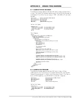
The profile of the borehole is constructed by using the cumulative sum of these
lateral displacements starting with the bottom segment. For instance, refer to
the figure to the left.
The total lateral displacements of the top of the uppermost segment from the
vertical line drawn through the bottom of the lower segment is:
D
total
= L
1
sin
1
+ L
2
sin
2
+ L
3
sin
3
EQUATION 3:
Total Lateral Displacement
4.3
TEMPERATURE CORRECTION
In a given installation, temperature effects can cause real changes of tilt;
therefore, each sensor is equipped with a device for measuring the sensor
temperature. This enables temperature-induced changes in inclination to be
distinguished from inclination due to other sources.
An important point to note is that sudden changes in temperature will cause
both the structure and the sensor to undergo transitory physical changes, which
will show up in the readings. The sensor temperature should always be
recorded, and efforts should be made to obtain readings when the instrument
and structure are at thermal equilibrium. The best time for this tends to be in the
late evening or early morning hours.
4.4
ENVIRONMENTAL FACTORS
Since the purpose of the inclinometer installation is to monitor site conditions,
factors that may affect these conditions should be observed and recorded.
Seemingly minor effects may have real influence on the behavior of the structure
being monitored and may give an early indication of potential problems. Some
of these factors include, but are not limited to, blasting, rainfall, tidal or reservoir
levels, excavation and fill levels and sequences, traffic, temperature and
barometric changes, changes in personnel, nearby construction activities,
seasonal changes, etc.
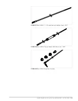
22:
FIGURE 22:
Installation Example
L
3
L
2
L
1


