©202
1
, GEOKON. All rights reserved.
Document Revision:
PP
| Release date: 1/28/21
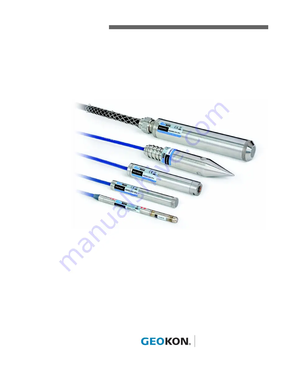
Model 4500 Series
Vibrating Wire Piezometer
Instruction Manual
Страница 1: ... 2021 GEOKON All rights reserved Document Revision PP Release date 1 28 21 Model 4500 Series Vibrating Wire Piezometer Instruction Manual ...
Страница 2: ......
Страница 3: ...ON is not responsible for any damages or losses caused to other equipment whether direct indirect incidental special or consequential which the purchaser may experience as a result of the instal lation or use of the product The buyer s sole remedy for any breach of this agreement by GEOKON or any breach of any warranty by GEOKON shall not exceed the purchase price paid by the purchaser to GEOKON f...
Страница 4: ......
Страница 5: ...EZOMETER PERFORMANCE 6 4 INSTALLATION 7 4 1 INSTALLATION IN STANDPIPES OR WELLS 7 4 2 INSTALLATION IN BOREHOLES 7 4 3 INSTALLATION IN FILLS AND EMBANKMENTS 9 4 4 INSTALLATION BY PUSHING OR DRIVING INTO SOFT SOILS 10 4 5 MODEL 4500H AND MODEL 4500HH TRANSDUCER 11 4 6 SPLICING AND JUNCTION BOXES 11 4 7 LIGHTNING PROTECTION 12 4 8 FREEZING PROTECTION 13 5 TAKING READINGS 14 5 1 GK 404 VIBRATING WIRE ...
Страница 6: ...3 A 1 4500 SPECIFICATIONS 23 A 2 4500CR SPECIFICATIONS 23 A 3 THERMISTOR 23 A 4 STANDARD PIEZOMETER WIRING 23 APPENDIX B THERMISTOR TEMPERATURE DERIVATION 24 B 1 3KΩ THERMISTOR RESISTANCE 24 B 2 10KΩ THERMISTOR RESISTANCE 25 APPENDIX C IMPROVING THE ACCURACY OF THE CALCULATED PRESSURE 26 APPENDIX D TYPICAL CALIBRATION REPORT 27 APPENDIX E MODEL 4500AR PIEZOMETER 28 APPENDIX F PIEZOMETER PRESSURE A...
Страница 7: ... ENTRY FILTER 10 FIGURE 6 LOW AIR ENTRY FILTERS ONLY 10 FIGURE 7 TYPICAL SOFT SOILS INSTALLATION 11 FIGURE 8 TYPICAL MULTI PIEZOMETER INSTALLATION 12 FIGURE 9 RECOMMENDED LIGHTNING PROTECTION SCHEME 13 FIGURE 10 GK 404 READOUT 14 FIGURE 11 LEMO CONNECTOR TO GK 404 14 FIGURE 12 GK 405 READOUT 15 FIGURE 13 VENTED PIEZOMETERS 19 FIGURE 14 TYPICAL CALIBRATION REPORT 27 FIGURE 15 4500AR PIEZOMETER 28 ...
Страница 8: ...IPLICATION FACTORS 17 TABLE 3 4500 VIBRATING WIRE PIEZOMETER SPECIFICATIONS 23 TABLE 4 4500CR VIBRATING WIRE PIEZOMETER SPECIFICATIONS 23 TABLE 5 STANDARD PIEZOMETER WIRING 23 TABLE 6 3KΩ THERMISTOR RESISTANCE 24 TABLE 7 10KΩ THERMISTOR RESISTANCE 25 TABLE 8 4500AR WIRING CHART 28 ...
Страница 9: ...7 EQUATION 3 TEMPERATURE CORRECTION 18 EQUATION 4 BAROMETRIC CORRECTION 18 EQUATION 5 CORRECTED PRESSURE CALCULATION 19 EQUATION 6 3KΩ THERMISTOR RESISTANCE 24 EQUATION 7 10KΩ THERMISTOR RESISTANCE 25 EQUATION 8 SECOND ORDER POLYNOMIAL EXPRESSION 26 EQUATION 9 LINEARITY CALCULATION 26 ...
Страница 10: ...VI ...
Страница 11: ...wo coils one with a magnet insert the other with a pole piece insert are installed near the vibrating wire In use a pulse of varying frequency swept frequency is applied to these coils causing the wire to vibrate primarily at its resonant frequency When the excitation ends the wire continues to vibrate During vibration a sinusoidal signal is induced in the coils and transmitted to the readout box ...
Страница 12: ...piezometer is experiencing zero atmospheric pressure This is what is known as the initial zero reading 3 Verify that the initial zero reading for the piezometer is compatible with the factory supplied zero reading on the calibration report 4 Carefully measure and mark the cable where it will lie at the top of the borehole well or standpipe once the piezometer has reached the desired depth The piez...
Страница 13: ...ing the filter and the space above it entirely with water To speed up the saturation process remove the filter from the piezometer by carefully twisting and pulling on the filter housing assembly or unscrewing the point of the piezometer for model 4500DP Hold the piezometer with the filter facing up and fill the space above the diaphragm with water Slowly replace the filter housing allowing the wa...
Страница 14: ...bing with approximately two inches five centimeters of water 3 Attach the other end of the tube to the hand vacuum pump 4 While holding the transducer so that the water rests on the filter but does not enter the pump squeeze the hand pump to initiate a vacuum inside the tubing This will draw the air out of the filter and the area behind it replacing it with water A vacuum of 20 to 25 Hg 50 to 65 c...
Страница 15: ... Handle the transducer with care during the installation procedure Despite taking every precaution to ensure that the transducer arrives unharmed it is possible for the zero to shift during shipment due to rough handling However tests have shown that though the zero may shift the calibration factors do not change Therefore it is doubly important that an initial no load zero reading be taken prior ...
Страница 16: ...eter by a measured increment 5 Record the reading on the readout box at the new depth 6 Using the factory calibration factor calculate the change in water depth 7 Compare the calculated change in depth with the measured depth increment The two values should be roughly the same ALTERNATIVE METHOD USING A DIP METER 1 Lower the piezometer tip to a measured depth below the water surface 2 Allow 15 to ...
Страница 17: ...alled in wells or standpipes where an electrical pump or cable is nearby Electrical interference from these sources can cause unstable readings If unavoidable it is recommended that the piezometer be placed inside a piece of steel pipe In situations where packers are used in standpipes special care should be taken to avoid cutting the cable jacket with the packer as this could introduce a possible...
Страница 18: ...l between the piezometer zones When using tamping tools special care should be taken to ensure that the piezometer cable jackets are not cut during installation as this could introduce a possible pressure leak in the cable INSTALLATION B The borehole is filled from the collection zone upwards with an impermeable bentonite grout 4 FIGURE 4 Typical Borehole Installations INSTALLATION C It should be ...
Страница 19: ...Green FMGM proceedings Oslo 2003 Copies are available from GEOKON 4 3 INSTALLATION IN FILLS AND EMBANKMENTS GEOKON piezometers are normally supplied with direct burial cable suitable for placement in fills such as highway embankments and dams both in the core and in the surrounding materials For installations in non cohesive fill materials the piezometer may be placed directly in the fill or if la...
Страница 20: ...ter filter 6 FIGURE 6 Low Air Entry Filters ONLY 4 4 INSTALLATION BY PUSHING OR DRIVING INTO SOFT SOILS The Model 4500DP piezometer is designed to be pushed into soft soils In soft soils it can be difficult to keep a borehole open The 4500DP may eliminate the need for a borehole altogether The unit is connected directly to the drill rod AW EW or other and pressed into the ground either by hand or ...
Страница 21: ...o the 1 4 18 NPT female port by placing a wrench on the flats provided on the transducer housing Avoid tightening onto a closed system the process of tightening the fittings could overrange and permanently damage the transducer If in doubt attach the gauge leads to a readout box and take readings while tightening For an easier and more positive connection to the transducer PTFE plumber s tape on t...
Страница 22: ...ith epoxy to waterproof the connections When properly made this type of splice is equal or superior to the cable in strength and electrical properties Contact GEOKON for splicing materials and additional cable splicing instructions Junction boxes and terminal boxes are available from GEOKON for all types of applications In addition portable readouts and dataloggers are also available Contact GEOKO...
Страница 23: ...struments will be read manually with a portable readout no terminal box a simple way to help protect against lightning damage is to connect the cable leads to a good earth ground when not in use This will help shunt transients induced in the cable to ground away from the instrument 9 FIGURE 9 Recommended Lightning Protection Scheme 4 8 FREEZING PROTECTION If the water around the piezometer freezes...
Страница 24: ... clips on the leads to the matching colors of the sensor conductors with blue representing the shield bare 3 To turn on the GK 404 press the On Off button on the front panel of the unit The initial startup screen will display 4 After a delay the GK 404 will start taking readings and display them based on the settings of the Pos and Mode buttons The unit display from left to right is as follows The...
Страница 25: ...to place and then twist the outer ring of the male connector until it locks into place 5 2 2 CONNECTING SENSORS WITH BARE LEADS Attach the flying leads to the bare leads of a GEOKON vibrating wire sensor by connecting each of the clips on the leads to the matching colors of the sensor conductors with blue representing the shield bare 5 2 3 OPERATING THE GK 405 Press the power button on the Readout...
Страница 26: ...ument Since the resistance changes with temperature are large the effect of cable resistance is usually insignificant For long cables a correction can be applied equal to approximately 48 5Ω per km 14 7Ω per 1000 at 20 C Multiply these factors by two to account for both directions 2 Look up the temperature for the measured resistance in Appendix B ...
Страница 27: ...polynomial In many cases the difference is minor The calibration report gives the pressure in certain engineering units These can be converted to other engineering units using the multiplication factors shown in Table 2 2 TABLE 2 Engineering Units Multiplication Factors Note Due to changes in specific gravity with temperature the factors for mercury and water in the above table are approximate 6 2...
Страница 28: ...responds to changes in atmospheric pressure Corrections may be necessary particularly for the sensitive low pressure models For example a barometric pressure change from 29 to 31 inches of mercury would result in approximately one psi of error or 2 3 feet if monitoring water level in a well It is advisable to read and record the barometric pressure every time the piezometer is read Having an onsit...
Страница 29: ...liminate the effect of barometric pressure changes on water level measurements in wells reservoirs and boreholes that are connected directly to the atmosphere They are not to be used where pore water pressures are being measured The space inside the transducer is not hermetically sealed and evacuated as it is in the standard 4500 model piezometer instead it is connected via a tube integral within ...
Страница 30: ...onitor site conditions factors that can affect these conditions should always be observed and recorded Seemingly minor affects may have a real influence on the behavior of the structure being monitored and may give an early indication of potential problems Some of these factors include but are not limited to blasting rainfall tidal levels traffic temperature and barometric changes weather conditio...
Страница 31: ...lator Check for sources of nearby electrical noise such as motors generators antennas or electrical cables Move the piezometer cable away from these sources if possible Contact the factory for available filtering and shielding equipment The piezometer may have been damaged by overranging or shock Inspect the diaphragm and housing for damage The body of the piezometer may be shorted to the shield C...
Страница 32: ...22 TROUBLESHOOTING GEOKON ...
Страница 33: ...0 0 1500 0 3000 0 5000 0 10000 0 1 0 2 5 0 5 Resolution 0 025 F S 0 025 F S 0 025 F S 0 025 F S 0 05 F S 0 025 F S 0 01 F S Linearity3 0 5 F S Accuracy4 0 1 F S Overrange 1 5 Rated Pressure Thermal Coefficient 0 025 F S C 0 1 F S C 0 05 F S C 0 025 F S C 0 05 F S C 0 025 F S C 0 025 F S C Temperature Range 20 C to 80 C Frequency Range 1400 3500 Hz OD 75 19 05 mm 1 25 40 mm 75 19 05 mm 687 17 45 mm...
Страница 34: ...31 5 84 102 5 125 88 46K 38 8417 3 1363 44 321 2 85 99 9 126 82 87K 37 8006 4 1310 45 311 3 86 97 3 127 77 66K 36 7618 5 1260 46 301 7 87 94 9 128 72 81K 35 7252 6 1212 47 292 4 88 92 5 129 68 30K 34 6905 7 1167 48 283 5 89 90 2 130 64 09K 33 6576 8 1123 49 274 9 90 87 9 131 60 17K 32 6265 9 1081 50 266 6 91 85 7 132 56 51K 31 5971 10 1040 51 258 6 92 83 6 133 53 10K 30 5692 11 1002 52 250 9 93 81...
Страница 35: ... 571 2 106 247 0 138 119 4 170 63 3 202 36 2 234 18 971 11 4 725 43 1 480 75 555 3 107 241 1 139 116 9 171 62 1 203 35 6 235 18 090 12 4 543 44 1 432 76 539 9 108 235 3 140 114 5 172 61 0 204 35 1 236 17 255 13 4 368 45 1 385 77 525 0 109 229 7 141 112 1 173 59 9 205 34 5 237 16 463 14 4 201 46 1 340 78 510 6 110 224 3 142 109 8 174 58 8 206 33 9 238 15 712 15 4 041 47 1 297 79 496 7 111 219 0 143...
Страница 36: ...ity is calculated using the regression zero for R0 shown on the calibration report For example when P 420 kPa G R1 R0 0 1795 6749 9082 gives a calculated pressure of 418 8 kPa The error is 1 2 kPa equal to 122 mm of water Whereas the polynomial expression gives a calculated pressure of A 6749 2 B 6749 1595 7 420 02 kPa and the actual error is only 0 02 kPa or two millimeters of water Note If the p...
Страница 37: ...MODEL 4500 SERIES VIBRATING WIRE PIEZOMETER TYPICAL CALIBRATION REPORT 27 APPENDIX D TYPICAL CALIBRATION REPORT 14 FIGURE 14 Typical Calibration Report ...
Страница 38: ...he field in the same way that the Model 4500 standard piezometer is installed see Section 3 and Section 4 4500AR Piezometer Wiring is shown in Table 8 The three pair cable is wired in pairs with each pair comprising one colored and one black lead 8 TABLE 8 4500AR Wiring Chart Upon power up the gauge will immediately start to ring at the resonant frequency and will continue to ring until the power ...
Страница 39: ...ottom of the well does not agree with the water level measured directly by the dip meter This will happen when the specific gravity of the water is not 1 gm cc the water is brackish or muddy or both It will also occur when there is a flow of water up or down the borehole In addition if the piezometer is removed to make room for the dip meter the volume of the piezometer and cable displaces an equa...
Страница 40: ......
Страница 41: ......
Страница 42: ......
Страница 43: ......
Страница 44: ......