©20
20
, GEOKON. All rights reserved.
Document Revision: W | Release date: 8/4/20
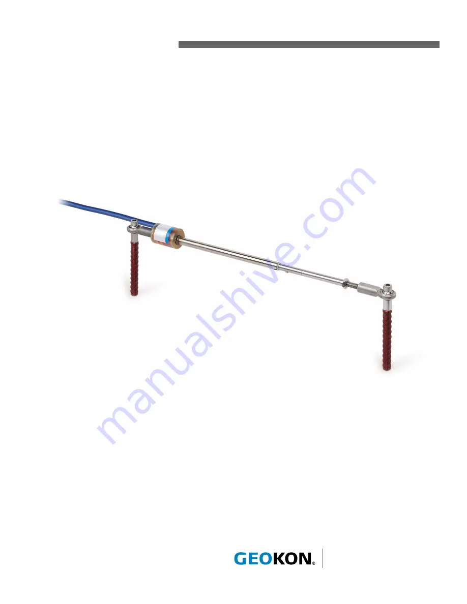
Model 4420 Series
Vibrating Wire Crackmeter
Instruction Manual
Страница 1: ... 2020 GEOKON All rights reserved Document Revision W Release date 8 4 20 Model 4420 Series Vibrating Wire Crackmeter Instruction Manual ...
Страница 2: ......
Страница 3: ...ON is not responsible for any damages or losses caused to other equipment whether direct indirect incidental special or consequential which the purchaser may experience as a result of the instal lation or use of the product The buyer s sole remedy for any breach of this agreement by GEOKON or any breach of any warranty by GEOKON shall not exceed the purchase price paid by the purchaser to GEOKON f...
Страница 4: ......
Страница 5: ...N FROM CORROSION 8 3 5 PROTECTION FROM ELECTRICAL NOISE 8 3 6 PROTECTION FROM SUNLIGHT AND TEMPERATURE CHANGES 8 3 7 LIGHTNING PROTECTION 8 4 TAKING READINGS 10 4 1 GK 404 VIBRATING WIRE READOUT 10 4 1 1 OPERATING THE GK 404 10 4 2 GK 405 VIBRATING WIRE READOUT 11 4 2 1 CONNECTING SENSORS WITH 10 PIN BULKHEAD CONNECTORS ATTACHED 11 4 2 2 CONNECTING SENSORS WITH BARE LEADS 11 4 2 3 OPERATING THE GK...
Страница 6: ...ACKMETERS 21 D 2 INSTALLING THE 3D ARRAY 21 D 3 MODEL 4420 3 CANTILEVER 3D ARRAY ALTERNATIVE 23 APPENDIX E MODEL 4420 3 LOW PROFILE CRACKMETER 25 E 1 INSTALLATION 25 E 1 1 PRELIMINARY TESTS 25 E 1 2 CRACKMETER INSTALLATION 26 E 2 SPECIFICATIONS 27 E 3 THERMISTOR 28 E 4 TEMPERATURE CORRECTION FACTOR 28 ...
Страница 7: ...ALLATION 7 FIGURE 8 LIGHTNING PROTECTION SCHEME 9 FIGURE 9 GK 404 READOUT 10 FIGURE 10 LEMO CONNECTOR TO GK 404 10 FIGURE 11 GK 405 READOUT 11 FIGURE 12 TYPICAL CRACKMETER CALIBRATION SHEET 14 FIGURE 13 TYPICAL 3D ARRAY TOP VIEW 21 FIGURE 14 TYPICAL 3D ARRAY FRONT VIEW 21 FIGURE 15 CANTILEVER 3D ARRAY TOP VIEW 23 FIGURE 16 CANTILEVER 3D ARRAY FRONT VIEW 24 FIGURE 17 MODEL 4420 3 VW LOW PROFILE CRA...
Страница 8: ...ERING UNITS CONVERSION MULTIPLIERS 13 TABLE 5 THERMAL COEFFICIENT CALCULATION CONSTANTS 15 TABLE 6 MODEL 4420 CRACKMETER SPECIFICATIONS 17 TABLE 7 3KΩ THERMISTOR RESISTANCE 18 TABLE 8 MODEL 4420HT 10KΩ THERMISTOR RESISTANCE 20 TABLE 9 3D ARRAY TYPICAL VERSION 21 TABLE 10 3D ARRAY CANTILEVER VERSION 24 TABLE 11 MODEL 4420 3 CRACKMETER SPECIFICATIONS 27 ...
Страница 9: ...EQUATION 3 DISPLACEMENT CHANGE 13 EQUATION 4 THERMALLY CORRECTED DISPLACEMENT CALCULATION 14 EQUATION 5 THERMAL COEFFICIENT CALCULATION 14 EQUATION 6 3KΩ THERMISTOR RESISTANCE 18 EQUATION 7 MODEL 4420HT 10KΩ THERMISTOR RESISTANCE 19 EQUATION 8 DISPLACEMENT CORRECTED FOR TEMPERATURE 28 ...
Страница 10: ...VI ...
Страница 11: ...n increase in tension which is sensed by the vibrating wire element The increase in tension strain of the wire is directly proportional to the extension of the shaft This change in strain allows the Model 4420 to measure the opening of the joint very accurately 1 FIGURE 1 Model 4420 Vibrating Wire Crackmeter Models 4420 3 4420 12 5 and 4420 25 differ slightly from the standard crackmeter in that t...
Страница 12: ...0 to 3000 digits Check electrical continuity using an ohmmeter Be sure to consider the following Resistance between the gauge leads should be approximately 180 ohms 10 ohms 128 ohms for the Model 4420HT Remember to add the cable resistance which is approximately 14 7Ω per 1000 ft 48 5Ω per km of 22 AWG stranded copper leads at 20 C Multiply this factor by two to account for both directions Resista...
Страница 13: ...Figure 12 supplied with the crackmeter shows factory readings at zero 25 50 75 and 100 of the range of extension These readings can be used as a guide to set the crackmeter in any part of its range either in anticipation of closure or opening of the crack Extend the crackmeter until the desired reading is obtained Model Range 1 Midrange To Monitor Extension To Monitor Compression 4420 3 mm 125 292...
Страница 14: ...using the spacings listed in Table 1 2 Grind sand or otherwise prepare the surface of the steel around the area of each weldable fixture 3 Position the welding fixtures on prepared surfaces 4 Verify the placement again then tack weld to the member 5 Remove the PVC slotted sleeve or dowel pin securing the transducer shaft 6 Thread the cap screw through the swivel bearing and through the half inch s...
Страница 15: ...ON USING EXPANSION ANCHORS 6 FIGURE 6 Installation using Expansion Anchors INSTALLATION INSTRUCTIONS 1 Determine the proper setting distance using the spacings listed in Table 1 2 Using a masonry drill or other suitable equipment drill two 10 mm 3 8 diameter holes 32 mm 1 25 deep at the proper locations 3 Insert the expansion anchors into the holes with the slotted end down 4 Insert the setting to...
Страница 16: ...while rotating the threaded rod Never rotate the transducer shaft beyond 180 degrees or gauge failure may result 2 After making an adjustment align the hole in the swivel bearing over the anchor and check the reading 3 Make adjustments until the desired reading displays on the readout 4 Push the cap screw through the swivel bearing and spacer 5 Tighten into the anchor 6 Re tighten the locking nut ...
Страница 17: ...nd are then filled with epoxy to waterproof the connections When properly made this type of splice is equal or superior to the cable in strength and electrical properties Contact GEOKON for splicing materials and additional cable splicing instructions Terminate a cable by stripping and tinning the individual conductors and then connecting them to the patch cord of a readout box Alternatively use a...
Страница 18: ...nstrument 4 Apply a coat of paint over the primed areas 3 5 PROTECTION FROM ELECTRICAL NOISE Be sure to install instrument cables as far away as possible from sources of electrical interference such as power lines generators motors transformers arc welders etc Cables should never be buried or run with AC power lines Doing so will cause the instrument cables to pick up the frequency noise from the ...
Страница 19: ...nsients away from the instruments See the figure below Plasma surge arrestors can be epoxied into the instrument cable close to the instrument A ground strap then connects the surge arrestor to an earth ground such as a grounding stake or the steel structure Consult the factory for additional information on available lightning protection 8 FIGURE 8 Lightning Protection Scheme Ground Connections Te...
Страница 20: ...clips on the leads to the matching colors of the sensor conductors with blue representing the shield bare 3 To turn on the GK 404 press the On Off button on the front panel of the unit The initial startup screen will display 4 After a delay the GK 404 will start taking readings and display them based on the settings of the Pos and Mode buttons The unit display from left to right is as follows The ...
Страница 21: ...ing of the male connector until it locks into place 4 2 2 CONNECTING SENSORS WITH BARE LEADS Attach the flying leads to the bare leads of a GEOKON vibrating wire sensor by connecting each of the clips on the leads to the matching colors of the sensor conductors with blue representing the shield bare 4 2 3 OPERATING THE GK 405 Press the power button on the Readout Unit After start up completes a bl...
Страница 22: ...esistance changes with temperature are large the effect of cable resistance is usually insignificant For long cables a correction can be applied equal to approximately 48 5Ω per km 14 7Ω per 1000 at 20 C Multiply these factors by two to account for both directions 2 Look up the temperature for the measured resistance in Appendix B For the 4420HT refer to Appendix C ...
Страница 23: ...e below TABLE 4 Engineering Units Conversion Multipliers For example the initial reading R0 at installation of a crackmeter is 2500 digits The current reading R1 is 6000 The gauge factor is 0 006223 mm digit The displacement change is Duncorrected 6000 2500 x 0 006223 x 21 78 EQUATION 3 Displacement Change Note that increasing readings digits indicate increasing extension To use the polynomial gau...
Страница 24: ...UXFWLRQ DEOH HQJWK 7HPSHUDWXUH 7HFKQLFLDQ PHWHUV DOLEUDWLRQ DWH 2FWREHU FWXDO LVSODFHPHQW PP DXJH 5HDGLQJ VW FOH DXJH 5HDGLQJ QG FOH YHUDJH DXJH 5HDGLQJ DOFXODWHG LVSODFHPHQW LQHDU UURU LQHDU 6 DOFXODWHG LVSODFHPHQW 3RO QRPLDO UURU 3RO QRPLDO 6 5HDGLQJ 3RVLWLRQ 00 PP GLJLW PP LQHDU DXJH DFWRU 5HJUHVVLRQ HUR 3RO QRPLDO DXJH DFWRUV DOFXODWH E VHWWLQJ DQG 5 LQLWLDO ILHOG HUR UHDGLQJ LQWR WKH SRO QRPL...
Страница 25: ...member combined with the changes in temperature from initial to current readings to determine thermal effects of the mass or member 5 3 ENVIRONMENTAL FACTORS Because the purpose of using a crackmeter is to monitor site conditions factors which may affect these conditions should always be observed and recorded Seemingly minor effects may have a real influence on the behavior of the structure being ...
Страница 26: ...e shaft is fully retracted with the alignment pin inside the alignment slot the readings will likely be unstable because the vibrating wire is under tensioned Is there a source of electrical noise nearby Likely candidates are generators motors arc welding equipment high voltage lines etc If possible move the instrument cable away from power lines and electrical equipment or install electronic filt...
Страница 27: ...5 12 mm 0 50 25 mm 1 50 mm 2 100 mm 4 150 mm 6 200 mm 8 300 mm 12 Resolution 0 025 FSR Linearity 0 25 FSR Thermal Zero Shift 0 05 FSR C Stability 0 2 yr under static conditions Overrange 115 FSR Temperature Range 20 to 80 C 5 to 175 F Frequency Range 1400 3500 Hz Coil Resistance 180Ω 10Ω Cable Type Two twisted pair four conductor 22 AWG Foil shield PVC jacket nominal OD 6 3 mm 0 250 Cable Wiring C...
Страница 28: ... 5 84 102 5 125 88 46K 38 8417 3 1363 44 321 2 85 99 9 126 82 87K 37 8006 4 1310 45 311 3 86 97 3 127 77 66K 36 7618 5 1260 46 301 7 87 94 9 128 72 81K 35 7252 6 1212 47 292 4 88 92 5 129 68 30K 34 6905 7 1167 48 283 5 89 90 2 130 64 09K 33 6576 8 1123 49 274 9 90 87 9 131 60 17K 32 6265 9 1081 50 266 6 91 85 7 132 56 51K 31 5971 10 1040 51 258 6 92 83 6 133 53 10K 30 5692 11 1002 52 250 9 93 81 6...
Страница 29: ...outer diameter of the epoxy The standard spacer supplied with anchors as shown in Figure 5 and Figure 6 is about 12 7 mm 500 therefore interference between the epoxied area and the mounted surface may occur To ensure this doesn t happen either rotate the assembly 180 degrees on its axis or use the larger supplied spacers 4420HT crackmeters are supplied with a high temperature thermistor that has a...
Страница 30: ...68 45 1 385 77 525 0 109 229 7 141 112 1 173 59 9 205 34 5 237 16 463 14 4 201 46 1 340 78 510 6 110 224 3 142 109 8 174 58 8 206 33 9 238 15 712 15 4 041 47 1 297 79 496 7 111 219 0 143 107 5 175 57 7 207 33 4 239 14 999 16 3 888 48 1 255 80 483 2 112 213 9 144 105 3 176 56 7 208 32 9 240 14 323 17 3 742 49 1 215 81 470 1 113 208 9 145 103 2 177 55 7 209 32 3 241 13 681 18 3 602 50 1 177 82 457 5...
Страница 31: ...re by means of a bracket or by direct mounting using expansion anchors D 2 INSTALLING THE 3D ARRAY ANCHOR SPACING For spacing distances refer to Table 1 in Section 2 2 1 When setting the gauge position using a portable readout refer to Table 1 in Section 2 2 1 to determine the proper position Range 9 A Length Midrange B Height C Length D Dimension E Dimension 25 mm 1 342 90 mm 13 50 384 56 mm 15 1...
Страница 32: ...tted sleeve or dowel pin securing the transducer shaft 5 Place the spacers on top of the anchors and attach the 5 625 long stainless steel bar to the anchors using the provided threaded rods lock washers and nuts Note The spacers used here are 1 8 3 2 mm shorter than the others to accommodate the width of the bar 6 Drill another 3 8 10 mm diameter 1 25 32 mm deep holes one directly below the 1 4 2...
Страница 33: ...both ends will be upright in relation to the break Two expansion anchors are supplied with this part located 1 1 4 apart and no spacers are required A percentage of the transducer s range can be established by tightening or loosening the nuts on the long threaded rod The actual height of the crackmeters above the surface is determined by the spacers and is proportional to the range of the sensor t...
Страница 34: ...ABLE 10 3D Array Cantilever Version For detailed information about the 4420 3 low profile crackmeter refer to Appendix E Range 10 A Length Midrange B Height C Length D Dimension E Dimension 25 mm 1 342 90 mm 13 50 53 98 mm 2 125 558 80 mm 22 34 93 mm 1 375 28 58 mm 1 125 ...
Страница 35: ...17 Model 4420 3 VW Low Profile Crackmeter Layout E 1 INSTALLATION E 1 1 PRELIMINARY TESTS Perform a preliminary check by completing the following 1 Connect the gauge to a readout box using the instructions in Section 4 1 2 Observe the displayed readout which usually will be between 1800 and 2500 digits The temperature reading should match the ambient temperature Checks of electrical continuity can...
Страница 36: ...ows 4 Using Loctite cement on the threads screw the reference disc into one of the threaded expansion anchor holes until it is tight in the anchor 5 Loosen the jam nuts on the oval point set screw Using the wrench provided back off the set screw so that it will not make contact with the reference surface when the gauge is mounted Note A one inch set screw is provided for installations where 75 or ...
Страница 37: ... suggestions are given assuming the two sides of the joint are on the same plane when the instrument is installed If there is a major discrepancy between the two sides contact geokon to determine if a custom solution is required 10 Once the reading is set tighten the locknuts to secure the set screw 11 In areas of high traffic the gauge should be protected by a cover plate For more information see...
Страница 38: ...ely one digit per C To calculate the displacement corrected for temperature use the equation below Dcorrected G R1 R0 T1 T0 EQUATION 8 Displacement Corrected for Temperature The temperature effect shown above is for a low profile crackmeter that has not been installed yet and is very minor The actual temperature effect of the installed instrument can be arrived at empirically only by simultaneous ...
Страница 39: ......
Страница 40: ...GEOKON 48 Spencer Street Lebanon New Hampshire 03766 USA Phone 1 603 448 1562 Email info geokon com Website www geokon com GEOKON is an ISO 9001 2015 registered company ...